Making light tubes for real
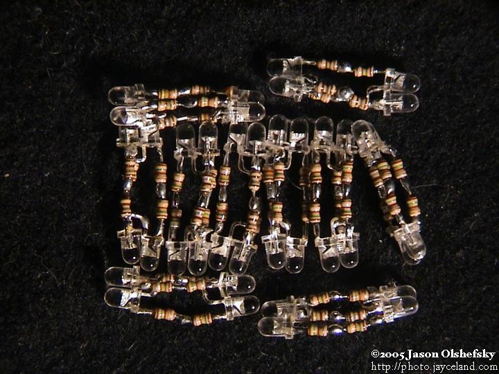
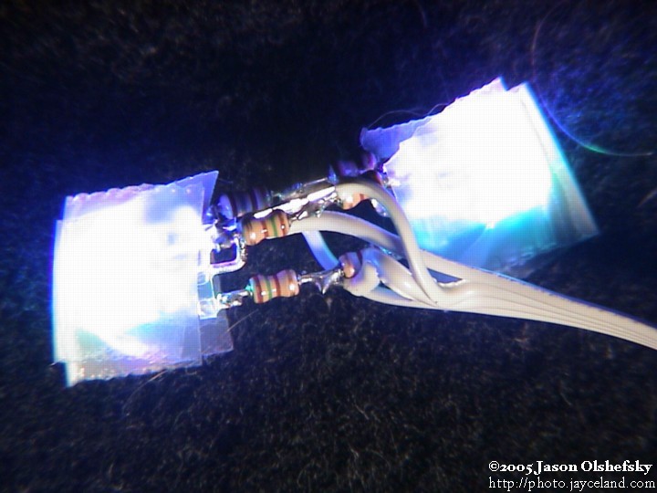
Posted: 2005-July-30 Filed under: Lighting, Projects, The Bike With 2 Brains Leave a comment »I assembled all the LED blocks assembly-line style. I got a system down and it didn't take too long to get 10 pairs assembled (a total of 20 clusters with 2 LED's in each cluster capable of emitting 3 colors.) The three resistor leads were about the same length so I used a penny as a conductor and tested all the clusters, fixing the few that are dead.
On the 31st, I made a couple passes on how to get the LED's to light up the eyes. Each eye has a pipe angle welded on the back that extends to a hole in the front; I have pupils with a short length of tubing that is glued into a short length of pipe that threads into the angle. The other end of the angle is open and is just the right size to accomodate the 1/2" polyethylene tubing with a very snug fit. I eventually figured out that the LED clusters are small enough to snake through the interior of the pipe angle so I just put them on long pigtails and I'll shove them into the pupil tubing to light it up.
By spacing the clusters evenly, I end up with 5 pairs facing in opposite directions, and the middle pair is right at the apex of the curve of the frame. Perfect. I started wiring them up like I did with the spiral bike tubing, except with address lines too. I needed to address 11 common cathodes (the 10 lights in the tube plus the one for the eye) along with 3 anodes (red, green, and blue) so I decided to run two ribbon cables: 8-conductors and 6-conductors. The 8-conductor would run the whole way with the three anodes and the eye cathode on the middle 4 conductors and then I'd use the two outside pairs to address the next two clusters. Likewise, the 6-conductor wire would address the remaining 6 cathodes.
I soldered the wires onto each cluster and taped each to a short length of 1/4" polyethylene tubing with clear tape — I did this on the spiral bike because it tended to shove the ribbon cable to the edge of the larger tube so it wouldn't block the light. Once I got done, I had a length of flopsy segments of 1/4" tubing with LED's in between each segment, a lot of tape, and ribbon cables. However, once I tried to snake it through the tube, it was just a little too big. I couldn't get the thing through. I tried pushing it, pulling it with a wire snake, adding silicone lubricant, sucking it with the vacuum cleaner, sucking it with the vacuum pump I have (using a pig made from larger tubing), and finally pulling it really hard with a soldered loop using the wire snake. I got about halfway and couldn't get any further. I took it back apart and found that I had ripped out some of the wires and it would never have worked anyway. I got a little annoyed for a bit, but realized that I could use ribbon cable for the common red, green, and blue anodes and then use wire-wrapping wire for the cathodes as they'll only carry a maximum of 60mA — the farthest lights might get a little dim, but it'll fit in the tube.
I got the wire-wrap solution knocked off in less time than I thought (including the repairs to the broken LED's — I still didn't manage to permanently break any of them.) The new setup looked better and using a similar technique with the wire snake, it slid in place with a modest amount of effort. One of the clusters didn't light so I had to take it apart and fix a bad solder joint, but other than that, the whole thing is addressable.
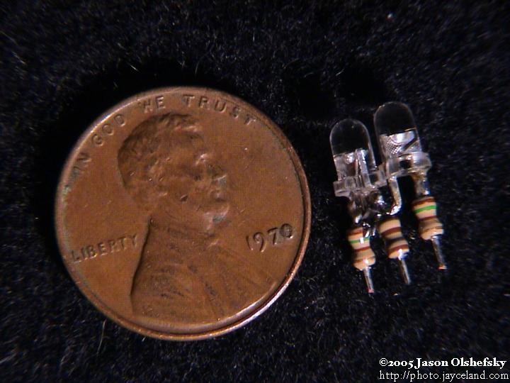
Even a penny from when dinosaurs roamed the Earth was a great way to test each of the clusters and to demonstrate their small size.
Spiral bike and light test
Posted: 2005-July-28 Filed under: Lighting, Projects, The Bike With 2 Brains Leave a comment »I was unable to kick the welding-geek habit and I accidentally made a frame for a spiral bike out of one piece of pipe. I'll be bringing it to Burning Man, and I used the light tubes as a proof-of-concept for my lighting idea. It's somewhat different in that the lights are all wired together (I can't address each cluster) but I do have the ability to change the colors using a control box behind the seat. It also has little headlights and a tail light, so it's safe to ride on the road (har har.) The digital camera on the camcorder was pretty bad so they don't enlarge (there's no point … the resolution wasn't there — I need my film camera, but I don't want to pay for the developing for just a couple shots.)
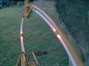
The spread of light through the tubing is easier to see when it's darker but then you can't see the frame.
Lights, camera, action
Posted: 2005-July-26 Filed under: Lighting, Projects, The Bike With 2 Brains Leave a comment »I worked on doing some tests of the lighting circuits. I am working on a bike for Burning Man and I'm going to use the same lighting technique, so I got a chance to try out what I want to do. I started with the red/blue 3mm LED's and the green 3mm LED's from LSDiodes.com. I decided to wire them in opposing pairs so I wouldn't have to space them as close (I figure the glow from an LED travels about 1 foot down the polyethylene tubing, so I can get away with spacing them out every 2 feet if I make a pair that shine away from one another.) It really wasn't too bad at all … here's the photo essay:
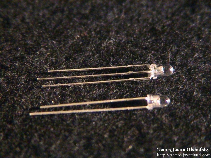
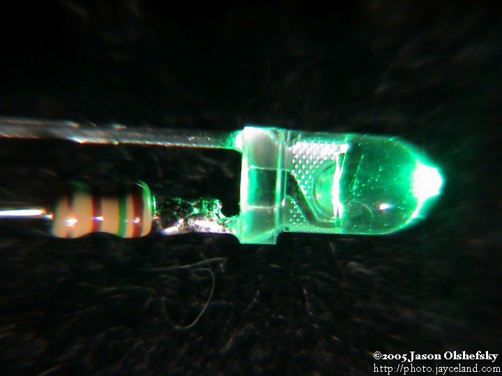
Here's the LED's as they're shipped. The red/blue is on the top; the pin on the side that's flat on the lens is the red anode, the other side is the blue anode, and the middle is the common cathode. On the green, the flat indicates the cathode.
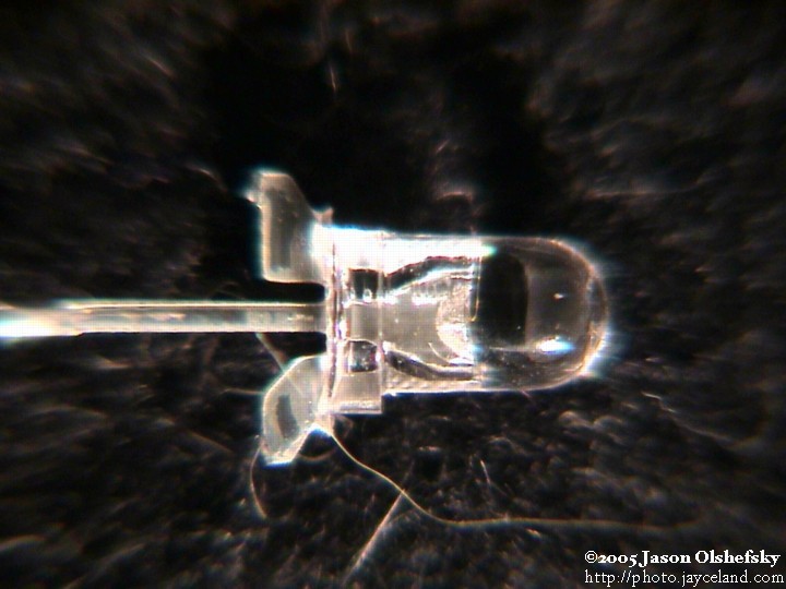
I cut the leads short on the LED so the resistors can be soldered close; this eliminates the need for using insulation because the leads can't be bent to short out anymore. Plus it's compact.
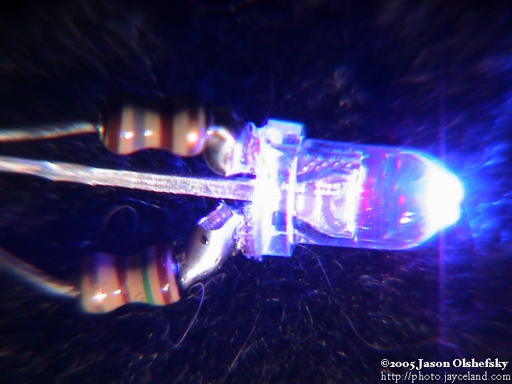
The red/blue LED's need two resistors; the red side gets a 180 ohm resistor and the blue gets 150 ohms.
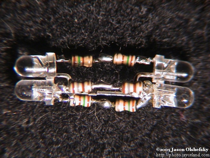
Here's what the finished pair looks like. I'll have to remember that I want to address each cluster, not the whole thing, so I shouldn't solder the cathodes together.
The next step was getting the ribbon cable inside the 3/8" inside-diameter tubing. Initially I tried just stuffing it in but it ended up being all floppy inside the tube. I bought some 1/4" outside-diameter tubing, taped the ribbon cable to it, and then stuffed it through. It works a lot better for two reasons: first, the ribbon cable lays flat, and second, the light assemblies are hard to push down the tube — I was using a piece of stiff wire, but with the additional small tubing, I can just guide it through without a push-rod.
Bought a new MP3 player
Posted: 2005-July-26 Filed under: Audio, Projects, The Bike With 2 Brains Leave a comment »In the process of shopping around for more tubing stuff for the lights, I stopped at Goodwill Fashions (376 Jefferson Rd., in Jefferson Plaza) and found they had an MP3 player for $25 so I picked it up. It's a Memorex MMP8560 with 128MB RAM. With 4 times more RAM than the Digisette, I'll be able to put on more music stuff. However, the interface to get it to start is more complex so I'll probably need to use the computer chip to run it (whereas the old player needed one button to be pressed to start, the new one needs to be powered on first and then started with the play button.)
The good news is that it only draws 40 mA. If I use a linear regulator from 12 volts to get to 1.5 volts (it uses a single AAA alkaline, not a NiMH cell) I'll only have to get rid of around 450 mW of power as heat which was as good as I got with the buck converter anyway. (Remember that the rationale there was to pick a higher-than-audio frequency and the transistor tended to go linear. I might try the buck converter again anyway.)
Frying the stupid MP3 player
Posted: 2005-July-25 Filed under: Audio, Projects, The Bike With 2 Brains Leave a comment »I spent about 3 hours working on the circuit to try and get a decent 1.2-volt output. I went through several transistors and some trial-and-error. Once I got to a point where I thought I'd see how things were working, I noted that the indicator light on the MP3 player was just staying on. I tried installing the battery but I got the same thing. Oddly, I can connect it to the computer and read the flash memory just fine. Hopefully it'll "heal" if I leave it disconnected for a while.
I guess I can use bit-modulation
Posted: 2005-July-24 Filed under: Lighting, Projects, The Bike With 2 Brains Leave a comment »Not only did I get too few 150-ohm resistors (I bought 30 of each, and I'll need 60 of the 150-ohm's.) I also decided to go with the bit-modulation anyway. The circuit I have in mind is essentially 3 banks of up to 30 LED's, so I can just multiplex between the red, green, and blue. I ordered several MIC5822 8-Bit Serial-Input Latched Drivers — they contain a cascadable shift register with an 8-bit latch and the outputs can sink up to 150 mA to ground.
Originally, I anticipated making a capacitor matrix that would keep the LED's from depleting and multiplexing the analog outputs on the PIC controller to charge the capacitors. It might have worked, but this bit-modulation system is way better — even if it flickers a little.
Powering the stupid MP3 player
Posted: 2005-July-18 Filed under: Audio, Projects, The Bike With 2 Brains Leave a comment »I worked on the audio system some more. I had an unfortunate setback: the LM217 I have is apparently dead, so it won't be the nice 1.2 volt reference. However, the rest of the system works fine and I successfully played audio through the speakers. I figure I can use one of the op-amp's as a voltage regulator. I cut holes in the electronics case to accomodate the phone connectors for speakers.
I used a couple diodes in series and a 4.7K resistor to create a 1.2 volt reference … I'll feed it through an op-amp at unity gain to get a stable source for the MP3 player … maybe with some capacitors if the charging circuit is too noisy.
Unfortunately, I had problems getting 1.2 volts to the MP3 player and eventually had to swap operational amplifiers twice. I finally got it set up and discovered that the MP3 player draws 200 mA. It never dawned on me to check, but that's indeed what it draws when it's running off the battery — it's not too bad at 240 mW, but by using a linear regulator, I have to dump the remaining 2.2 watts as heat — I was hoping to get the whole system (lights included) to operate on less than 5 watts total, so this is a big waste.
I built a twin-T oscillator to feed an op-amp as a comparator to make a pretty efficient pulse-width-modulated power supply. I came up with a circuit that uses 0.002 microfarad capacitors all around, 1K resistors on the resistor-tee, a 470 ohm resistor on the capacitor-tee, and a 4.7K resistor on the collector. It creates about a 0.3V peak-to-peak 40 KHz sine wave. When I wired it up final, I had to do a couple swaps of capacitors (i.e. a ceramic capacitor marked with "223" is 22 * 10^3, not 2.2 * 10^3, so my 2200 picofarad capacitors were really "222") I only had a bunch of "102" (1000 picofarad) capacitors so I had to use 10K resistors on the other tee of the circuit which gave me a nice 40 KHz output again. (The problem was the 2200 pF capacitors were physically quite large and I wanted to pack things into a smaller circuit.)
I got the pulse-width-modulated output to work somewhat, but it pretty much just goes into a linear mode when I try to make it work and again draws 200 mA from the 12-volt supply. I had configured a second op-amp to provide closed-loop feedback to adjust the PWM output, so the voltage was right, but it looks like the op-amps just can't make a 40 KHz square wave and the transistor is running in a linear mode.
I took a quick crack at making a buck DC-DC converter and managed to get it working in short order. The circuit required 40 mA at 12 volts, and I know about 5 mA of that is for the rest of the electronics, so 35 mA at 12 volts is 420 mW — so with the MP3 player using 240 mW, I managed to get to about 50% efficiency. Unfortunately, even 180 mW dissipation on a little transistor is quite a lot so I'll need to get a bigger one with a better heat sink. However, I'm happy that things function!
Fitting the cases for the electronics
Posted: 2005-July-16 Filed under: Frame, Projects, The Bike With 2 Brains Leave a comment »I layed out how everything is going to fit on the rear deck. I have a "Zero" brand box for most of the electronics and I'll have to set it about 5 inches off the surface with the hinges to the back so the combination will be accessible below the battery box and so it'll clear the rear frame bar. I bought some blue spraypaint and painted some of the parts — the color isn't exactly right but it's close enough for the accessories.
Starting on the audio system
Posted: 2005-July-15 Filed under: Audio, Projects, The Bike With 2 Brains Leave a comment »I received a pair of computer speakers from Jan and Shannon to use on the project. I took them apart, removed the electronics, put some expanding foam in the tuned ports (to help waterproof them) and painted the speaker cones (again for waterproofing.)
I took a look at the parts I have and figure I can just make a daughter-board for the MP3 player which would control its operation, provide power, and contain the audio amplifier. I decided to use a comparator to detect when there's a signal: compare against some small positive voltage and send the output to charge a capacitor through a diode which would discharge with a high R-C time constant. When the capacitor voltage drops below a set level, a second comparator would trigger the play button to be pressed.
I got back to working on the amplifier and started looking at the TDA1520A because I have several lying around — they're a 20-watt mono audio amplifier chip that requires very few external components. Unfortunately, the designers decided to neglect the car-audio market and it's rated to work as low as 15 volts. I figured I'd try it with 12 volts … I wired it all up and found that it just wouldn't function right. Darn.
It dawned on me that I should just use the amplifier from the computer speakers — it's already wired up, it's designed to work with the specific speakers, and it originally ran off 9 VAC so I can get about the same using 12 volts into the AC input … admittedly with some superfluous components, but who cares?
I decided to use telephone jacks to connect the speakers to the main control box as they seem to be easy to make water resistant I sealed up the holes on the speaker cabinets and prepared them for a phone-wire connection.
I took apart the MP3 player and connected wires to the play button and to the data activity light. The activity light pulses around 1 volt whenever the unit is playing, and that should be easier than detecting audio output. I set it up with a connector to plug into a board and I set up a metal bracket to hold the amplifier board, the MP3 player, and the auto-start board. I added DC-blocking capacitors between the MP3 player's output and the amplifier input as the DC levels are likely to be different and the system wasn't designed with a common ground in mind.
Upholstering 101
Posted: 2005-July-15 Filed under: Frame, Projects, The Bike With 2 Brains Leave a comment »I had picked up a couple futon mattresses from the trash. One of them was red on one side and black on the other. I separated the two sides and pulled all the stuffing out — it's cotton batting that wraps around three layers of urethane foam. I cleaned the pieces of fabric.
I used plywood for the seat bottoms and back, cut to fit the mounting holes. I cut pieces of foam and wrapped each in batting then cut sheets of red fabric, wrapped them around the seat-side of the seats and stapled it all in place. I just kept finding where the fabric was slack, pulled it tight, and stuck in another staple.
In my mind I wanted something like lips which is why I picked red. I decided to cut notches in the seat back to imply lips. I want to maintain the industrial-organic appearance and very fluffy, organic-looking lips would seem out of place so I gave the "suggestion" of lips. I haven't had a chance to put it together to see how it looks.

Recent Comments