Paleocord v1.21 Testing Results
Posted: 2017-January-29 Filed under: Paleocord Adapter 1 | Tags: Altoids tin, KiCAD, micro-USB, paleocord, Paleocord Adapter 1, RJ11, RJ14, RJ25, RJ45, USB, USB-A, USB-B Leave a comment »Although it's been on my desk for the better part of a month, I finally had a chance to check out the latest version 1.21 of the Paleocord Adapter 1 board. (Note that the version numbers correlate to the internal CVS version numbers I'm using, so they are not sequential.)
I made the following changes:
- The outermost pair on the RJ25 (the 6-pin version of the telephone jack) is now connected to the first line of the opposite connector. Thus, "line 3" of the Main jack is wired to "line 1" of the Aux jack and vice versa. If you use an RJ14 or RJ11 socket or cable, these pins are not used and won't bother that type at all.
- I changed the surface-mount pad sizes for the micro-USB-B connectors so now they're much easier to solder by hand.
- I moved the USB-A jacks inward 0.075" each and that makes them fit an Altoids tin much easier.
- I added a gap between the headphone jacks so now the panel-mount nuts can be installed without hitting one another.
- I corrected the labeling on the color codes so solid-color wires are "rings" and white/color stripes are "tips".
- I redesigned the labeling to reference the central RJ45 connectors' pin numbers instead of color-coded pairs. At first I didn't like it, but it has grown on me as it's more complete and clear. I think it was just a case of it being "new".
For the most part, this makes the project a satisfactory "done". Nonetheless, here's a couple updates I might make in future revisions:
- Looking through my bin of adapters, I realized if I move the headphone jacks just a little farther apart, they should work with airplane headset adapters.
- If I can find a way, I'll add pads to install a stereo headphone jack so a monaural connection would be wired correctly.
- I'm on the fence about the "on the go" (OTG) jumper. I don't think there exists a 5-pin to 5-pin micro-USB cable, so it isn't actually good for anything (e.g. to notify a device to host USB instead of act as a device.) Nonetheless, someone might want access to that spare pin and they could solder onto the pad. If I do anything, I'll remove the jumper bridge and replace it with a through-hole pad so it's easier to make use of.
See the Paleocord 1 main page for updated details and ordering information.
Paleocord v1.15 Testing Results
Posted: 2016-December-5 Filed under: Paleocord Adapter 1 | Tags: Altoids tin, KiCAD, paleocord, Paleocord Adapter 1, RJ11, RJ14, RJ25, RJ45, USB, USB-A, USB-B Leave a comment »I finally got and tested a few Paleocord 1 boards from OSHPark and found a couple minor problems. For reference, the source files are still available—v1.15, 2016-Nov-7.
The good news is I tested all the connectivity and it is correct. The bad news is the labeling is wrong. There was no pin #7 on the main RJ45 jacks, and I had reversed all the wire color-codes: all the solid-color wires should have been rings and the white/color stripes tips. I also didn't like how the labeling appeared once it was finally on the silkscreen. And when I was fitting it to an Altoids tin, it was a pretty tight fit since the USB-A connectors stuck out pretty far. I had tested using headphone jacks with threaded barrels, and the nuts for those jacks would actually touch.
So the following are changes for the new release v1.21, 2016-Dec-4:
- Wire outer pair on RJ25 jack (formerly unconnected; if you use an RJ14 or RJ11 socket or cable, it will still be.)
- Move USB-A jacks inward 0.075" each.
- Add a gap between the headphone jacks.
- Correct color codes so solid-color wires are "rings" and white/color stripes are "tips".
- Redesign labeling to reference the central RJ45 connectors' pin numbers instead of color-coded pairs.
See the Paleocord 1 main page for updated details and ordering information.
ADC Adapter Board Shared at OSHPark
Posted: 2014-January-16 Filed under: ADC adapter | Tags: ADC, OSHPark Leave a comment »For those looking to just purchase an adapter board by the current design I've made, here is the link to the ADC Adapter Board at OSH Park. Good luck.
Quirk about the ADC Connector
Posted: 2013-July-24 Filed under: ADC adapter | Tags: ADC, Apple Display Connector, ground, power supply, solder 9 Comments »I started having problems with the ADC display using the adapter I built. It worked fine for quite some time then the display started to shut itself off and not be recognized by the system. Sometimes it would work to plug the cables back in.
At first I thought it was the power supply I was using. I don't have specs on it, but the problem surfaced when the temperature climbed. The computer area was hovering around 90°F, and I assumed the power supply was sporadically failing. I bought a new-to-me 24V 1.8A supply for my 17" monitor (I think that might be a bit on the low-side, but it was only a couple dollars at a thrift store.) The problem persisted almost immediately. So I figured the monitor might be fried.
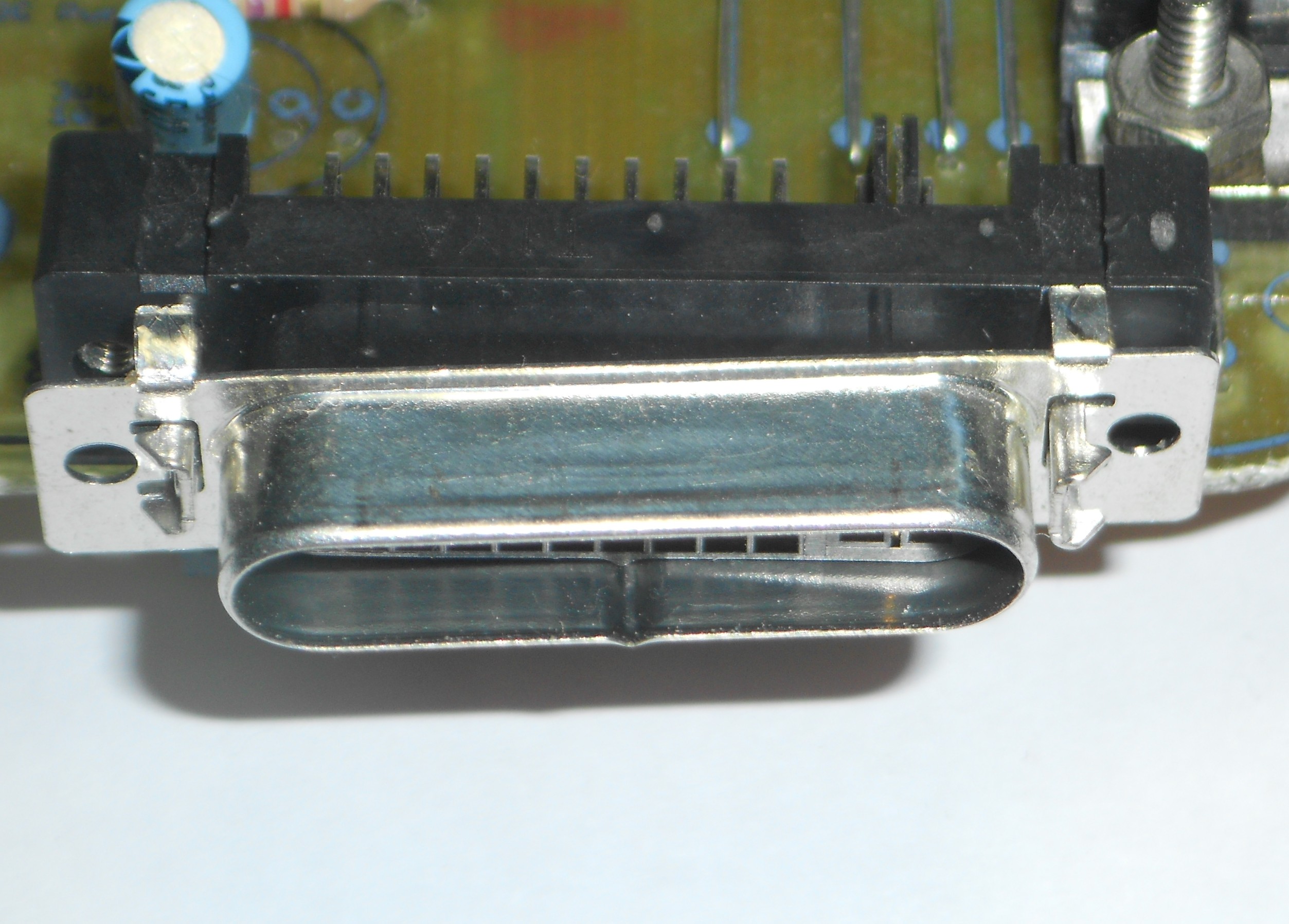
The ADC connector shield is loose.
I had noticed the shield on the ADC connector on the board was not connected to the ground very well. I didn't think much of it — after all, there were half a dozen ground wires already. But on a whim, I thought I'd add a couple dabs of solder and give it a solid connection to the pins soldered onto the board. Surprisingly, that did the trick. So far it's been 2 days and the monitor has not flaked out! It may be the power supply is on the low-side to begin with (24V) and without the additional ground of the shield, the voltage drop crept too high in the other wires for the monitor to function.
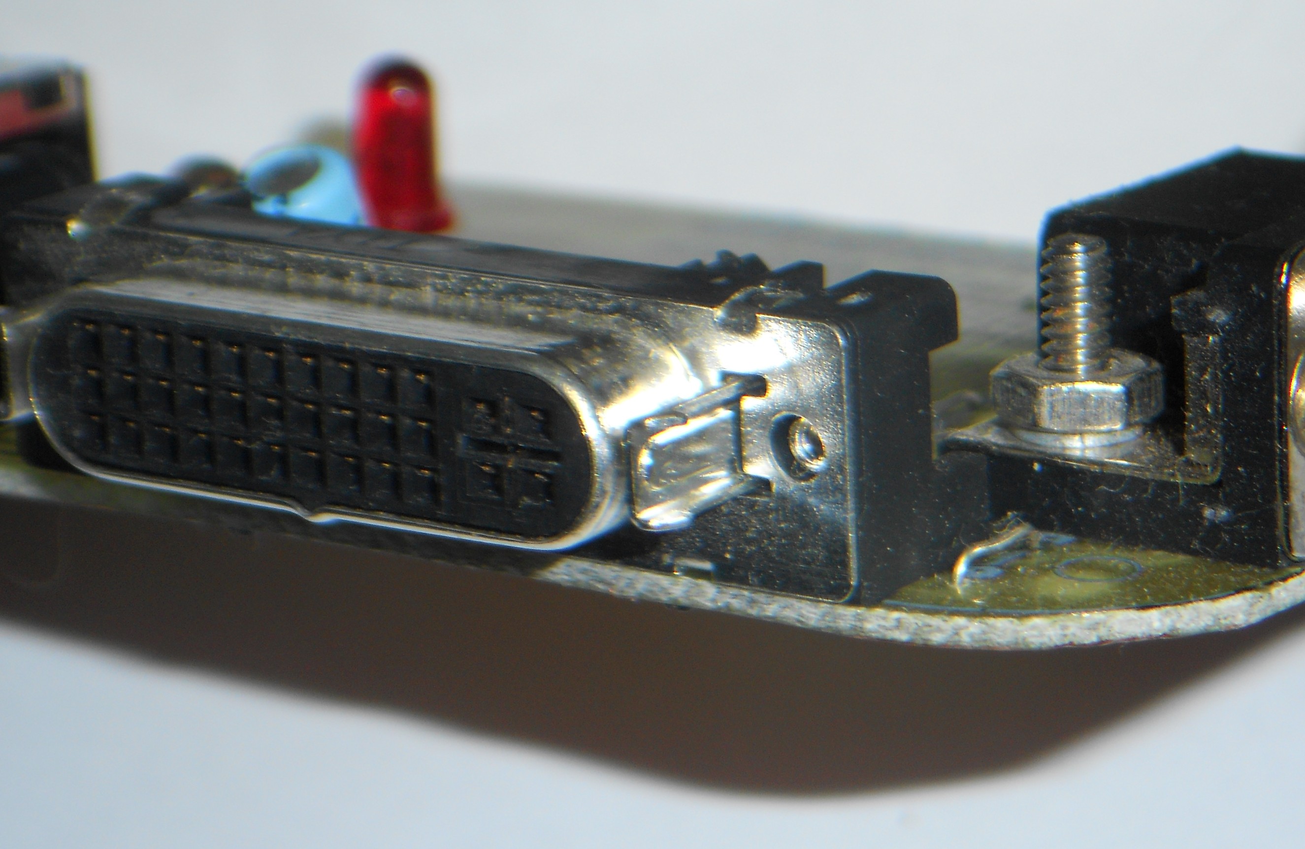
ADC connector shield.
In any case, if you are observing sporadic problems where the monitor would shut off, apparently losing power, check the shield on the ADC connector and make sure it has a solid ground.
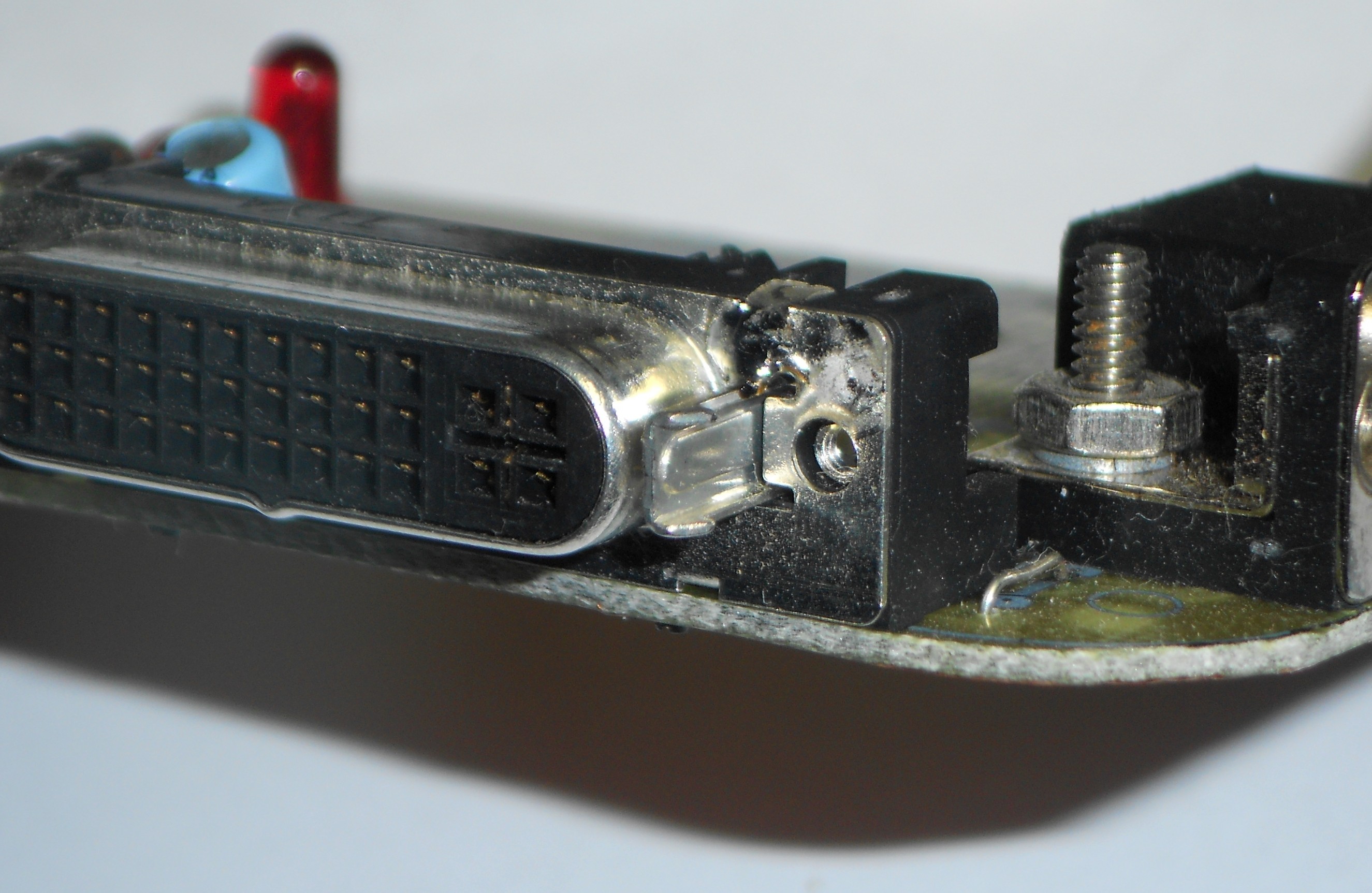
Solder added to ADC connector shield.
Update August 7, 2013: Not so fast. I am still having problems where the monitor will switch off and not come back on. Most recently, I had to unplug the power for 15 minutes as well as the connection to the computer before it came back to working. I'm not sure what it is, but the ground is not the only fault going on here …
Files for OSHPark
Posted: 2013-May-31 Filed under: ADC adapter | Tags: ADC, BatchPCB, DVI, Open Source Hardware, OSHPark, OSHW, VGA 9 Comments »I got a message that BatchPCB has closed and been replaced by OSHPark and the author requested I update the Gerber files. I tried simply renaming the files and put them in a new ZIP. I uploaded them to OSHPark and the visualization of the boards look good. I don't intend to do a test purchase, but please let me know how it turns out. Anyway, here's the ZIP archive with the Gerber files. Enjoy. (You will need to save the ZIP archive and upload it to OSHPark yourself as there is no storefront like there was on BatchPCB.)
Video and USB Connectors Library
Posted: 2013-February-25 Filed under: ADC adapter | Tags: ADC, CadSoft, DVI, EAGLE, library, Open Source Hardware, OSHW, USB, VGA Leave a comment »And, per the open source hardware requests, here is a ZIP file containing a parts library for CadSoft's EAGLE schematic design software containing an ADC connector, VGA connector, DVI connector, and a few USB connectors. These are missing from the default libraries so one could edit and make their own ADC adapter board.
I had success wiring up the various connectors, but you may need to adjust dimensions to meet DRC requirements with whatever method you are getting circuit boards made. Naturally, there is no warranty with this library.
ADC Adapter: EAGLE Schematic and Board
Posted: 2013-February-24 Filed under: ADC adapter | Tags: ADC, Apple, Apple Display Connector, circuit board, EAGLE, Open Source Hardware, OSHW, schematic Leave a comment »I got a request for the source files for the ADC Adapter board — after all, I indicated the project is open source. So here they are: 2012403ADCAdapter. It's a ZIP containing the schematic and board file for the CadSoft's EAGLE schematic design software. I have since switched to KiCad for all my projects but don't intend to get around to updating this one.
2012-Apr-3 ADC Adapter Board
Posted: 2012-October-18 Filed under: ADC adapter | Tags: ADC, BatchPCB, DVI, OSHW, VGA Leave a comment »After reviewing the boards I got back from BatchPCB, I made a few changes:
- Fix bug where DVI pin 15 (ground) was unconnected. This didn't actually cause a problem in my tests, but it should be connected.
- Increase ratio of documentation (e.g. visible when project is completed, does not apply to placement) to a minimum thickness of 0.01" (0.06" letters at 18% thickness ratio.)
- Move VGA text so it does not run over a via.
- Rearrange central text so it does not run over vias.
- Add bigger polarity marks for the monitor power bypass capacitor set.
This is noted as version "2012-Apr-3" on the silkscreen. You can buy it here.
ADC Adapter Board with Minor Bugs
Posted: 2012-April-3 Filed under: ADC adapter | Tags: ADC, Advanced Circuits, BatchPCB, DVI, ground, Open Source Hardware, OSHW, VGA Leave a comment »I finished up my ADC-DVI-VGA version that fits in an Altoids tin and sent it to BatchPCB. I prefer to use American labor, so I got a quote from Advanced Circuits, but the prices work out: it’s about $400 to start at any quantity (e.g. 10 is about $40 each) down to $10/each for 100. I couldn’t justify it in case (a) there was a bug, and (b) whether I could sell more than 5 to make up for it.
While I was waiting for it, I fiddled around in the design to make sure it was right. I realize I should have checked the design first, and, running the electrical rule check (ERC) I found I had left the DVI connector ground unconnected. D'oh! Fortunately there are half a dozen other grounds which (usually) get all tied together, so I was lucky and when I wired one up, it worked perfectly the first time. (Note that this is the 2012-Feb-29 version with only 4 copies around.)
I'm updating the design and will send it off to BatchPCB and open it up for sale. I'll also post the design files as my intent is for this project to be an Open Source Hardware (OSHW) project.
Recent Comments