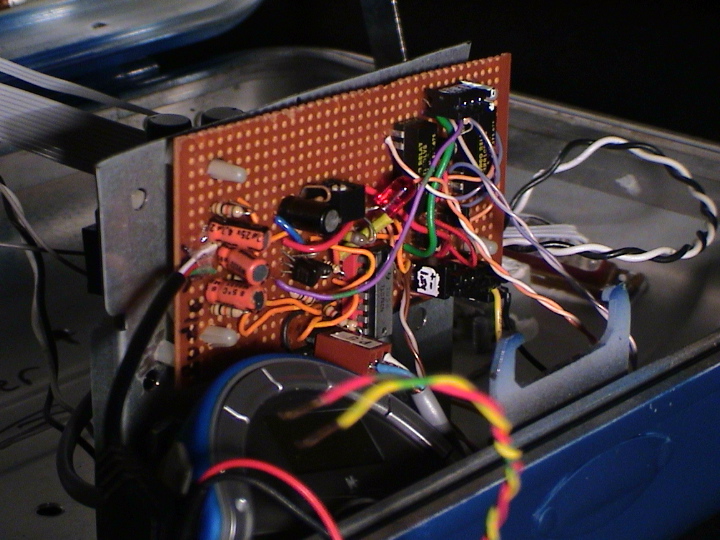
Just a picture of the sound board
Posted: 2005-August-21 Filed under: Audio, Projects, The Bike With 2 Brains Leave a comment »Remote controlling the MP3 player
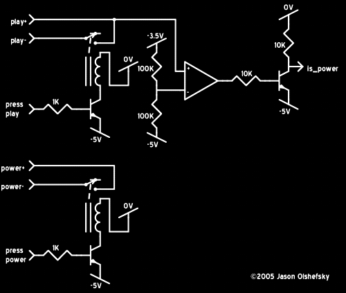
Posted: 2005-August-17 Filed under: Audio, Projects, The Bike With 2 Brains Leave a comment »I finished up the circuitry for both being able to actuate the play and power buttons from the computer and for detecting when the MP3 player is on. I'm sure you'll all be so amused that I used these ancient reed relays to do so — I opted against optoisolators because I wanted to have something that less could possibly go wrong — but I didn't know how they were wired. I couldn't find any info on the "Dunco Relay" MRR1CDLV8 on the Internet, and while I could identify some of the pins by a resistance check, but I wasn't sure exactly what was what. I did, however note that the patent number was printed on the cases. A couple guesses about what the smearily stamped ink said, and I came up with patent #3,575,678 … the images at the US Patent Office website entry for 3,575,678 show in much better detail how the thing works … plus it was patented in 1971.
Anyway, here's that circuit:
Musicians of The Bike With 2 Brains
Posted: 2005-August-16 Filed under: Audio, Projects, The Bike With 2 Brains Leave a comment »Here's the songs and artists who graciously provided the music and sound for the Bike With 2 Brains … in order that they submitted works to me. I had put a call out to a few musicians in the Rochester area based on how I thought they could interpret the bike project. None of them saw it before creating the music, so it was only based on the description I provided back in May.
Autumn in Halifax
Autumn In Halifax is David Merulla. He does this great work with a digital looping machine and guitar. It's somewhere between experimental and acoustic — his lyrics are richly poetic as well, only subtly providing any literal meaning. He provided 5 tracks and I used them all:
- September
- The Schwin Vista
- Estacios
- Twenty One January
- The Jockeys Last Night
You can recognize his songs as the ones that use guitar and distorted variations on guitar. Also, he asked that I include the copyright information: c/p autumn in halifax/colossal heart music 2003-2005(ascap).
BELBIVDEVOIVOD A.K.A. PAUL BURKE
BELBIVDEVOIVOD A.K.A. PAUL BURKE consists of the real-life Paul Burke. He uses a sampler with a complex array of loops and effects pedals to create droning synthesized sound with very organic variations. He provided the track "Kissyface" which I felt perfectly captured the combination I was looking for: it feels like the Bike With 2 Brains, it has a spirit that is strongly Rochester, and its style is reminiscent of Burning Man itself.
Gaybot
Gaybot consists of Brian Blatt, Chris Wicks, and Matty Sonar. Not only do they have (arguably) the coolest band name ever, they're one of the most laid-back bands ever. They play a cacophonous blend of spoken word, electronic effects, and repetition that makes for a generally good but disorienting experience. When I caught up with Brian and Matty and asked if they were planning to make some music, they said to just take something from a CD. I had their EP from 2004 (I think … it's just a CD-R with "Gaybot" written on it and I got it in 2004) and I liked the second track — which was the reason why I wanted them to be involved, but with that permission, I decided to use "Gaybot EP Track 2" as I named it.
XLTieRack
XLTieRack is Jon Peone. He plays synthesizers and guitars through effects and loops, often using sounds created when equipment is pushed beyond the limits for which it was designed. His sound is compatible with that of BELBIVDEVOIVOD A.K.A. PAUL BURKE but his techniques are very different. He provided me with 4 tracks: a mix and the three component pieces that were used to create the mix. I liked "Bike 1" which is the background drone of the mix and I liked "BikeMix," the final product so I included those two tracks.
Jason Olshefsky
When I sent out the e-mail I indicated that I wanted to include my own track. I intended to record the sounds of dusk around here because I think it's so commonplace that people hardly notice, but on the Playa, it would be completely out of place. However, time constraints led me to a different path (darn … I'm falling into a pun.) I had been taking a walk around the block near my house to unwind. My street runs from East Henrietta Road (Route 15A) to Mount Hope (Route 15) — the two routes converge about a half-mile north of my house. I walk to 15A then head south to the Erie Canal which runs east and west across New York State … the pathway is now called the "Heritage Trail," but it's technically the towpath for the mules pulling barges. I descend the path to the edge of the canal about 35 feet below street level then walk along to Route 15, back up to street level, and back to my house.
I had noticed that the sound was like some kind of time-machine. In the morning when everyone is busy driving up and down the two streets, the contrast to the canal is dramatic. It is serene and completely decompressing. The sounds of the street fade almost completely away right in the middle then slowly build to the traffic crescendo on the other end.
I mused about the title a bit, but ended up with "The Edge Between 15A and 15." As a nerd, it's a literal interpretation of the city's boundary between Route 15A and Route 15. However, from my photographic background, it can also refer to the space between pictures which are numbered on the negatives alternating between numerals and the previous frame number with an "A." What I think I accomplished is an audiograph of the walk in the morning. As an added bonus, listen for the sound of a squirrel jumping onto a nearby tree with an audible crunch.
Joe+n
Joe+n in this particular incarnation is just Joe Tunis. I met him in college then lost touch for ten years until I happened to go to one of the shows he set up for his record label, Carbon Records. His music rarely falls into any one category, although his forte is electric guitar and drums, usually in experimental-style usage. He also works with recordings and audio illusions. He created a piece called "In Search Of" and provided the following description:
symbiotic relationship: joe+n, tree-frogs and crickets. i just moved into a new house. it was sad leaving the old one. i grew to really _know_ the sound of the background. which insects sounds were around (most of the time), the birds that frequented our trees, the hum of nearby I490, and the railroad slightly further away. but being in the new house for about 2 weeks now, i'm getting to _know_ this backyard as well. the major addition to this soundscape is the return of the tree frogs. i grew to absolutely love, and NEED, these sounds back in my 4 years spent at RIT's Racquet Club apartments. my summers there were spent getting loaded with friends, playing music, and then walking around aimlessly at night, listening to the frogs. it made every summer blissful. but then one summer, they were gone. it was the sadness none-sound i'd ever heard. and now, they're back.
How to detect if the MP3 player is playing and making an MP3 of my own
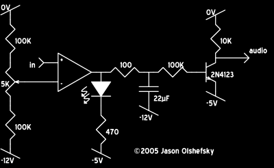
Posted: 2005-August-13 Filed under: Audio, Projects, The Bike With 2 Brains Leave a comment »It took me longer than I thought it would, but I finally got a circuit to detect audio output. This is the only way I can tell if the MP3 player is actually playing — the computer will need to turn on the MP3 player and then to set it to play. Anyway, the thing that took a while was doing tests with various capacitors and discharge resistors. I wanted at least 15 seconds of silence before the circuit would indicate silence. In retrospect, I probably should have had the computer handle that, but oh well. It's built now. I also added the LED so I can set the trimpot easier — it might have been a better idea to put in a switch or jumper, but I used a large resistor so the LED only consumes a few milliamps.
The other thing today in audio land was to edit the recording I made the other day and make an MP3. It wasn't too hard although I really have no audio editing software so I had to do it with video stuff. Anyway, it's titled "The Edge Between 15A and 15."
Hacking the MP3 player
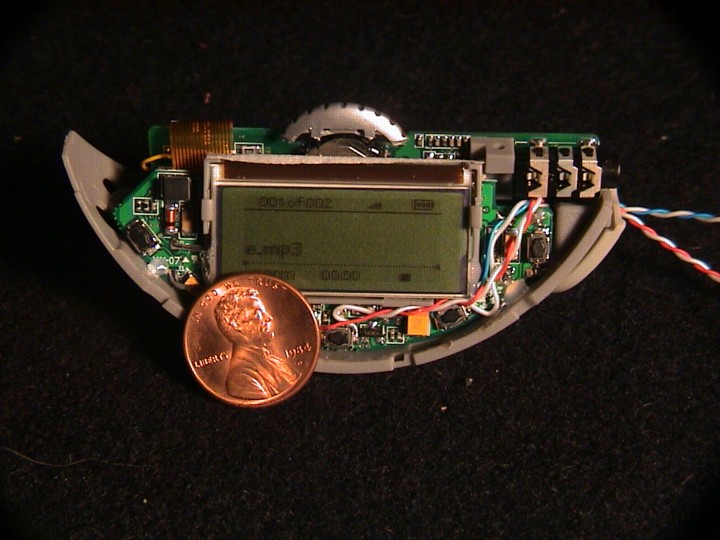
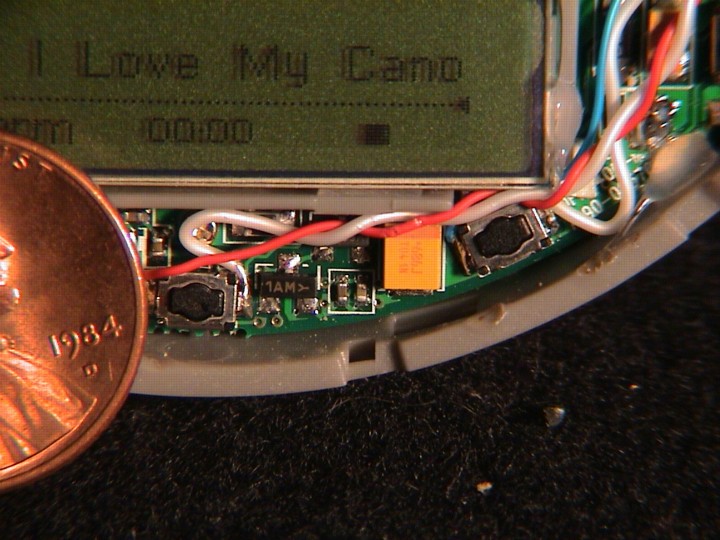
Posted: 2005-August-8 Filed under: Audio, Projects, The Bike With 2 Brains Leave a comment »I took apart the MP3 player and did some measurements on the switches.
| State | Power button | Play button |
| off | 1.5V/0V | 0V/0V |
| on | 3.2V/0V | 2.8V/0V |
| playing | 3.2V/0V | 2.8V/0V |
It's pretty convenient that I can detect power-on through the switch voltages. Whew. For playing I'll need to check that there's some signal on the output which could be a bit tricker. I think I'm going to compare to some arbitrarily low voltage and run the comparator output through a diode to a capacitor. The capacitor would discharge slowly with a resistor through the base-emitter junction of a transistor: the collector could be attached to a resistor to 5 volts — while playing, it would stay very close to 0 volts (logic 0) but if there was no ouput, it would slowly rise to 5 volts, eventually tripping whatever logic input.
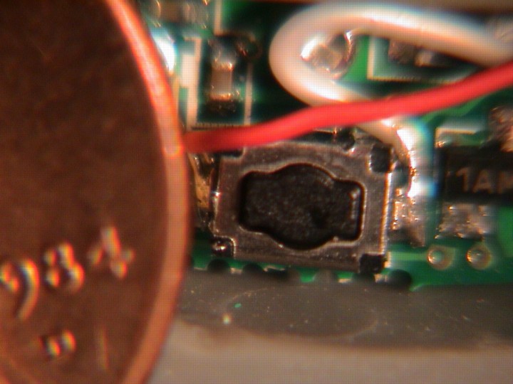
I wired up little wires to the switches and battery case to hook it to the logic circuits and power. What a pain to solder to this surface-mount stuff:
Finally sounds like it's working
Posted: 2005-August-6 Filed under: Audio, Projects, The Bike With 2 Brains Leave a comment »I'm using some DC-blocking capacitors to get the MP3 player output (which is grounded at -5V) to match the audio amplifier (grounded at -12V.) Unfortunately, I keep getting 1KHz noise from the switching supply. I tried going to the linear supply but that didn't work either. I even tried a big filter capacitor right at the MP3 player but no joy.
I figured out that the MP3 player was generating clean output but the speaker amplifier had issues with its ground being noisy. I tried a number of filtering techniques and such but came up dry. I decided to try with the LA4445 amplifier again: I figure I can bend the 2mm pins to fit the 0.10" spacing on the circuit boards I have. It dawned on me that I could probably make some kind of common-collector amplifier in a class A-B configuration.
I figure I can connect a resistor from emitter-to-base on each pole and one from base to a common input. The ratio of resistors defines the quiescent current and the values define the amplification. I may avan be able to do a push-pull with the 5-volt source for lower power and higher efficiency. I could set up the output to center around the -5V which is signal ground for the MP3 player. I thought about it for a while and decided to go with a common-emitter design with some biasing resistors and an op-amp — using the op-amp to compensate for the transistor switching.
First I tried the LA4445 because I thought it would be simpler. I spent an hour or so working, got everything wired up, but I took some shortcuts and the thing just won't work. Crap. Back to square one — again.
I decided to tinker with the transistors a little. I got to the point that I could generate output, but they won't stay on all the time in a true A-B configuration so it gets all noisy and such. I considered using some resistors and diodes to keep the transistors biased all the time.
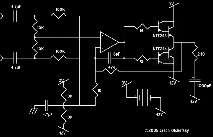
I fianlly got a viable solution. I used the same crappy design I used for the amplifier I built years ago which just drives a couple opposed Darlington transistors with an op-amp as feedback, although I did a better job of fixing the high-frequency oscillation problem. It ends up drawing about 400 mA (5 watts) with the MP3 player in-circuit and the amplifier at volume with both speakers driven in parallel. I suspect that the output is around 2 watts total or so, based on around 2 volts RMS (as measured by the oscilloscope) into 2 ohms. If it hits 2.5 volts, it's at 3.1 watts which I think is about peak.
Based on the circuit I used, the input is already self-centering around the midpoint of the power supply. The transistors need 1.2 volts peak-to-peak to maintain quiescent current, so the theoretical maximum output (going rail-to-rail) is +/- 5.4 volts; RMS voltage is 3.8 volts or 3.6 watts into 4 ohms. I tried to get away with a single op-amp to do voltage gain and to power the main amplifier. It seems to work but is even more twitchy than before … although I guess the noisy volume level is so quiet that you'd have to be right next to the speaker to discern it. Here's the circuit:
I had an op-amp I was using to generate a solid signal ground, but I didn't need it so I took it out. Anyway, at the 12-volt source, the audio section (with the MP3 player draws about 50mA and when it's at full volume, it peaks around 200mA, so I assume the output power is around 1.8 watts total consuming some 2.4 watts at peak volume. It kind of sounds like crap with a bit of fuzzy distortion from the transistor switching noise — if you know circuits, it should be pretty evident why:
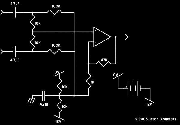
I got the amplifier wired and it works okay from the linear power supply but it's not working off the battery and I'm not sure why. It dawned on me that I can just use one of the op-amp's as a differential amplifier off the MP3 player and feed that into the prefabricated amplifier? I ended up with this simplified circuit:
The first experiment worked great so I rewired the circuit to take out all that extraneous crap to deal with the transistors and got it working again. It looks like I can get something like 3 watts of audio out of the thing, and the whole powered system typically takes around 2 watts at moderate volume.
It's just too bad I had to ditch the power transistors and heat sinks because they really looked cool.
Bought a new MP3 player
Posted: 2005-July-26 Filed under: Audio, Projects, The Bike With 2 Brains Leave a comment »In the process of shopping around for more tubing stuff for the lights, I stopped at Goodwill Fashions (376 Jefferson Rd., in Jefferson Plaza) and found they had an MP3 player for $25 so I picked it up. It's a Memorex MMP8560 with 128MB RAM. With 4 times more RAM than the Digisette, I'll be able to put on more music stuff. However, the interface to get it to start is more complex so I'll probably need to use the computer chip to run it (whereas the old player needed one button to be pressed to start, the new one needs to be powered on first and then started with the play button.)
The good news is that it only draws 40 mA. If I use a linear regulator from 12 volts to get to 1.5 volts (it uses a single AAA alkaline, not a NiMH cell) I'll only have to get rid of around 450 mW of power as heat which was as good as I got with the buck converter anyway. (Remember that the rationale there was to pick a higher-than-audio frequency and the transistor tended to go linear. I might try the buck converter again anyway.)
Frying the stupid MP3 player
Posted: 2005-July-25 Filed under: Audio, Projects, The Bike With 2 Brains Leave a comment »I spent about 3 hours working on the circuit to try and get a decent 1.2-volt output. I went through several transistors and some trial-and-error. Once I got to a point where I thought I'd see how things were working, I noted that the indicator light on the MP3 player was just staying on. I tried installing the battery but I got the same thing. Oddly, I can connect it to the computer and read the flash memory just fine. Hopefully it'll "heal" if I leave it disconnected for a while.
Powering the stupid MP3 player
Posted: 2005-July-18 Filed under: Audio, Projects, The Bike With 2 Brains Leave a comment »I worked on the audio system some more. I had an unfortunate setback: the LM217 I have is apparently dead, so it won't be the nice 1.2 volt reference. However, the rest of the system works fine and I successfully played audio through the speakers. I figure I can use one of the op-amp's as a voltage regulator. I cut holes in the electronics case to accomodate the phone connectors for speakers.
I used a couple diodes in series and a 4.7K resistor to create a 1.2 volt reference … I'll feed it through an op-amp at unity gain to get a stable source for the MP3 player … maybe with some capacitors if the charging circuit is too noisy.
Unfortunately, I had problems getting 1.2 volts to the MP3 player and eventually had to swap operational amplifiers twice. I finally got it set up and discovered that the MP3 player draws 200 mA. It never dawned on me to check, but that's indeed what it draws when it's running off the battery — it's not too bad at 240 mW, but by using a linear regulator, I have to dump the remaining 2.2 watts as heat — I was hoping to get the whole system (lights included) to operate on less than 5 watts total, so this is a big waste.
I built a twin-T oscillator to feed an op-amp as a comparator to make a pretty efficient pulse-width-modulated power supply. I came up with a circuit that uses 0.002 microfarad capacitors all around, 1K resistors on the resistor-tee, a 470 ohm resistor on the capacitor-tee, and a 4.7K resistor on the collector. It creates about a 0.3V peak-to-peak 40 KHz sine wave. When I wired it up final, I had to do a couple swaps of capacitors (i.e. a ceramic capacitor marked with "223" is 22 * 10^3, not 2.2 * 10^3, so my 2200 picofarad capacitors were really "222") I only had a bunch of "102" (1000 picofarad) capacitors so I had to use 10K resistors on the other tee of the circuit which gave me a nice 40 KHz output again. (The problem was the 2200 pF capacitors were physically quite large and I wanted to pack things into a smaller circuit.)
I got the pulse-width-modulated output to work somewhat, but it pretty much just goes into a linear mode when I try to make it work and again draws 200 mA from the 12-volt supply. I had configured a second op-amp to provide closed-loop feedback to adjust the PWM output, so the voltage was right, but it looks like the op-amps just can't make a 40 KHz square wave and the transistor is running in a linear mode.
I took a quick crack at making a buck DC-DC converter and managed to get it working in short order. The circuit required 40 mA at 12 volts, and I know about 5 mA of that is for the rest of the electronics, so 35 mA at 12 volts is 420 mW — so with the MP3 player using 240 mW, I managed to get to about 50% efficiency. Unfortunately, even 180 mW dissipation on a little transistor is quite a lot so I'll need to get a bigger one with a better heat sink. However, I'm happy that things function!
Starting on the audio system
Posted: 2005-July-15 Filed under: Audio, Projects, The Bike With 2 Brains Leave a comment »I received a pair of computer speakers from Jan and Shannon to use on the project. I took them apart, removed the electronics, put some expanding foam in the tuned ports (to help waterproof them) and painted the speaker cones (again for waterproofing.)
I took a look at the parts I have and figure I can just make a daughter-board for the MP3 player which would control its operation, provide power, and contain the audio amplifier. I decided to use a comparator to detect when there's a signal: compare against some small positive voltage and send the output to charge a capacitor through a diode which would discharge with a high R-C time constant. When the capacitor voltage drops below a set level, a second comparator would trigger the play button to be pressed.
I got back to working on the amplifier and started looking at the TDA1520A because I have several lying around — they're a 20-watt mono audio amplifier chip that requires very few external components. Unfortunately, the designers decided to neglect the car-audio market and it's rated to work as low as 15 volts. I figured I'd try it with 12 volts … I wired it all up and found that it just wouldn't function right. Darn.
It dawned on me that I should just use the amplifier from the computer speakers — it's already wired up, it's designed to work with the specific speakers, and it originally ran off 9 VAC so I can get about the same using 12 volts into the AC input … admittedly with some superfluous components, but who cares?
I decided to use telephone jacks to connect the speakers to the main control box as they seem to be easy to make water resistant I sealed up the holes on the speaker cabinets and prepared them for a phone-wire connection.
I took apart the MP3 player and connected wires to the play button and to the data activity light. The activity light pulses around 1 volt whenever the unit is playing, and that should be easier than detecting audio output. I set it up with a connector to plug into a board and I set up a metal bracket to hold the amplifier board, the MP3 player, and the auto-start board. I added DC-blocking capacitors between the MP3 player's output and the amplifier input as the DC levels are likely to be different and the system wasn't designed with a common ground in mind.

Recent Comments