The light tubes are done
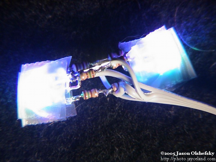
Posted: 2005-August-14 Filed under: Lighting, Projects, The Bike With 2 Brains Leave a comment »I needed to finish up the light tubes today for the demonstration in the afternoon. I wired all the pigtails from the end of the tube into a DB-25 connector. Since I had not labelled the wires, I had to test each LED so I could wire them on the connector in order. Not such a big deal. I got the whole setup mounted on the bike. For the demonstration (since I didn't have the computer finished) I just wired up a couple DB-25's to light up all the blue LED's that face backward. It looked pretty cool, especially at night.
Almost 100% done with the light tubes
Posted: 2005-August-11 Filed under: Lighting, Projects, The Bike With 2 Brains Leave a comment »I wired up the second light tube and had a case of deja-vu when I tried snaking it through the tubing: it was really tight and I kept breaking the wires I was pulling on. I used some silicone spray to try and get it going but it kept getting stuck. I eventually gave up, started on it the next day when I had some rest. I got it wired up and installed. I also found that I had a dead green LED in the original string so I replaced that. All I have to do now is to wire up the connectors … oh, and build the whole computer system.
A quick note about emergency lighting
Posted: 2005-August-8 Filed under: Lighting, Projects, The Bike With 2 Brains Leave a comment »I've been thinking about what would happen if the main battery went dead — the whole vehicle would go dark and silent. I had been thinking about adding separate markers on the steering tubes of the back wheels, but it would quite a bit of extra work. It dawned on me that I can set up emergency lighting with a relay and a couple batteries: as long as the power was on, the relay would stay on; if it shut off, the battery would connect to several of the lights on the string: i.e. far front, far rear, and the eyes … 6 lights at 20mA would be 120mA and would drain a 2200mAH battery in 18 hours, but if I got it down to say 10mA total, then it would last for 200 hours. If I went with green then it would be most visible. I dug up a very small relay with a 12-volt coil and it draws 15mA itself, but I found I could get it down to 7mA if I wired it in series with a capacitor (to let it latch) and a resistor (to keep it latched.)
I changed my mind and decided to make a pulse-width modulator with a low-power 555 timer and just hold the reset pin low via the control computer — if it failed, the 555 would start pulsing and drive the LED's.
Making light tubes for real
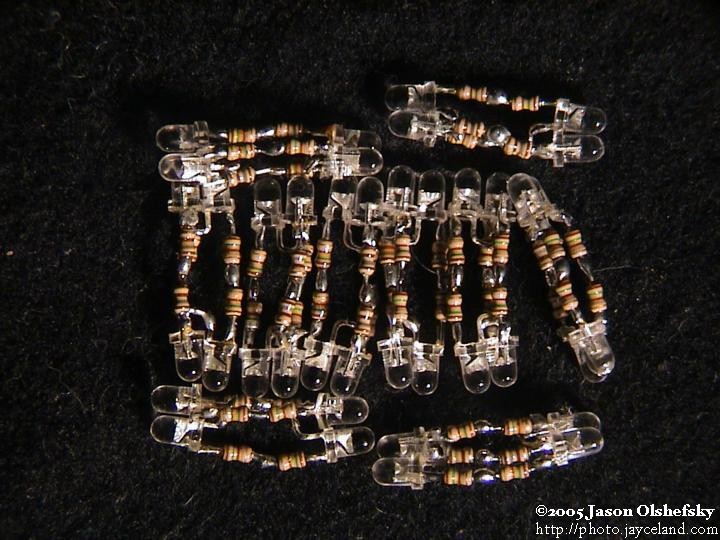
Posted: 2005-July-30 Filed under: Lighting, Projects, The Bike With 2 Brains Leave a comment »I assembled all the LED blocks assembly-line style. I got a system down and it didn't take too long to get 10 pairs assembled (a total of 20 clusters with 2 LED's in each cluster capable of emitting 3 colors.) The three resistor leads were about the same length so I used a penny as a conductor and tested all the clusters, fixing the few that are dead.
On the 31st, I made a couple passes on how to get the LED's to light up the eyes. Each eye has a pipe angle welded on the back that extends to a hole in the front; I have pupils with a short length of tubing that is glued into a short length of pipe that threads into the angle. The other end of the angle is open and is just the right size to accomodate the 1/2" polyethylene tubing with a very snug fit. I eventually figured out that the LED clusters are small enough to snake through the interior of the pipe angle so I just put them on long pigtails and I'll shove them into the pupil tubing to light it up.
By spacing the clusters evenly, I end up with 5 pairs facing in opposite directions, and the middle pair is right at the apex of the curve of the frame. Perfect. I started wiring them up like I did with the spiral bike tubing, except with address lines too. I needed to address 11 common cathodes (the 10 lights in the tube plus the one for the eye) along with 3 anodes (red, green, and blue) so I decided to run two ribbon cables: 8-conductors and 6-conductors. The 8-conductor would run the whole way with the three anodes and the eye cathode on the middle 4 conductors and then I'd use the two outside pairs to address the next two clusters. Likewise, the 6-conductor wire would address the remaining 6 cathodes.
I soldered the wires onto each cluster and taped each to a short length of 1/4" polyethylene tubing with clear tape — I did this on the spiral bike because it tended to shove the ribbon cable to the edge of the larger tube so it wouldn't block the light. Once I got done, I had a length of flopsy segments of 1/4" tubing with LED's in between each segment, a lot of tape, and ribbon cables. However, once I tried to snake it through the tube, it was just a little too big. I couldn't get the thing through. I tried pushing it, pulling it with a wire snake, adding silicone lubricant, sucking it with the vacuum cleaner, sucking it with the vacuum pump I have (using a pig made from larger tubing), and finally pulling it really hard with a soldered loop using the wire snake. I got about halfway and couldn't get any further. I took it back apart and found that I had ripped out some of the wires and it would never have worked anyway. I got a little annoyed for a bit, but realized that I could use ribbon cable for the common red, green, and blue anodes and then use wire-wrapping wire for the cathodes as they'll only carry a maximum of 60mA — the farthest lights might get a little dim, but it'll fit in the tube.
I got the wire-wrap solution knocked off in less time than I thought (including the repairs to the broken LED's — I still didn't manage to permanently break any of them.) The new setup looked better and using a similar technique with the wire snake, it slid in place with a modest amount of effort. One of the clusters didn't light so I had to take it apart and fix a bad solder joint, but other than that, the whole thing is addressable.
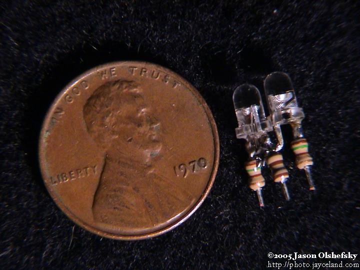
Even a penny from when dinosaurs roamed the Earth was a great way to test each of the clusters and to demonstrate their small size.
Spiral bike and light test
Posted: 2005-July-28 Filed under: Lighting, Projects, The Bike With 2 Brains Leave a comment »I was unable to kick the welding-geek habit and I accidentally made a frame for a spiral bike out of one piece of pipe. I'll be bringing it to Burning Man, and I used the light tubes as a proof-of-concept for my lighting idea. It's somewhat different in that the lights are all wired together (I can't address each cluster) but I do have the ability to change the colors using a control box behind the seat. It also has little headlights and a tail light, so it's safe to ride on the road (har har.) The digital camera on the camcorder was pretty bad so they don't enlarge (there's no point … the resolution wasn't there — I need my film camera, but I don't want to pay for the developing for just a couple shots.)
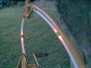
The spread of light through the tubing is easier to see when it's darker but then you can't see the frame.
Lights, camera, action
Posted: 2005-July-26 Filed under: Lighting, Projects, The Bike With 2 Brains Leave a comment »I worked on doing some tests of the lighting circuits. I am working on a bike for Burning Man and I'm going to use the same lighting technique, so I got a chance to try out what I want to do. I started with the red/blue 3mm LED's and the green 3mm LED's from LSDiodes.com. I decided to wire them in opposing pairs so I wouldn't have to space them as close (I figure the glow from an LED travels about 1 foot down the polyethylene tubing, so I can get away with spacing them out every 2 feet if I make a pair that shine away from one another.) It really wasn't too bad at all … here's the photo essay:
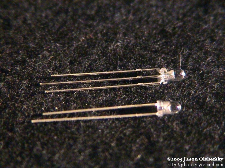
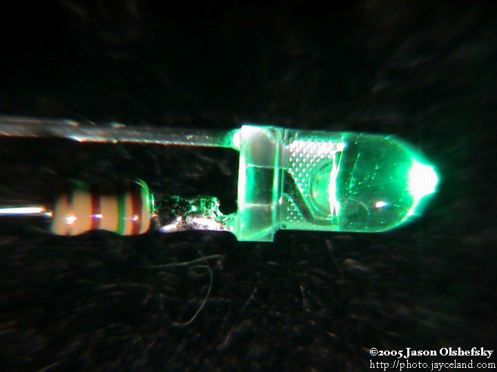
Here's the LED's as they're shipped. The red/blue is on the top; the pin on the side that's flat on the lens is the red anode, the other side is the blue anode, and the middle is the common cathode. On the green, the flat indicates the cathode.
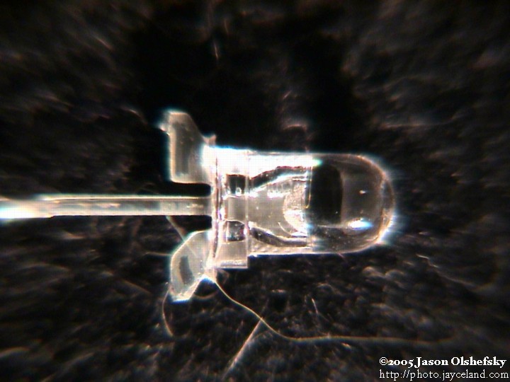
I cut the leads short on the LED so the resistors can be soldered close; this eliminates the need for using insulation because the leads can't be bent to short out anymore. Plus it's compact.
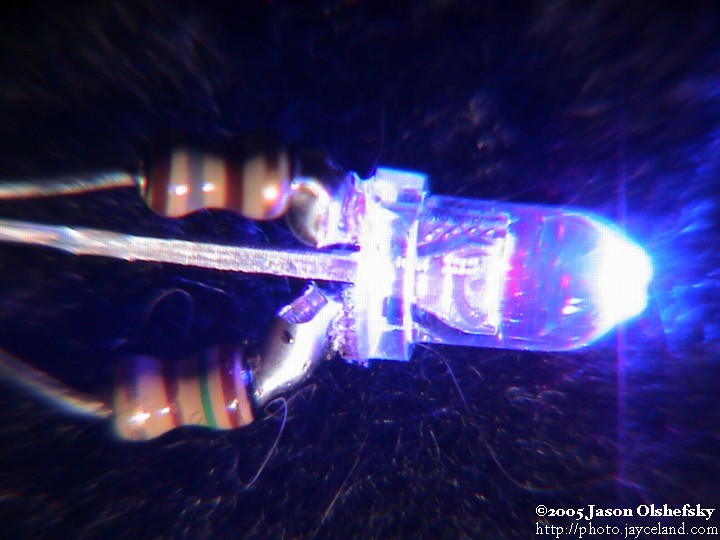
The red/blue LED's need two resistors; the red side gets a 180 ohm resistor and the blue gets 150 ohms.
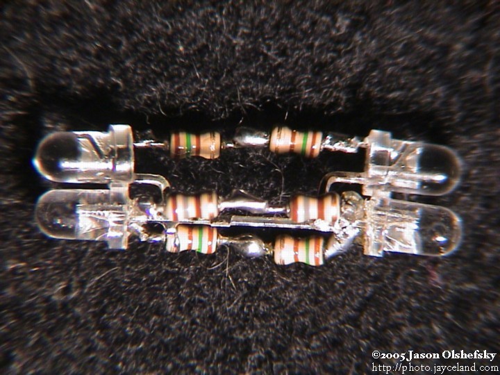
Here's what the finished pair looks like. I'll have to remember that I want to address each cluster, not the whole thing, so I shouldn't solder the cathodes together.
The next step was getting the ribbon cable inside the 3/8" inside-diameter tubing. Initially I tried just stuffing it in but it ended up being all floppy inside the tube. I bought some 1/4" outside-diameter tubing, taped the ribbon cable to it, and then stuffed it through. It works a lot better for two reasons: first, the ribbon cable lays flat, and second, the light assemblies are hard to push down the tube — I was using a piece of stiff wire, but with the additional small tubing, I can just guide it through without a push-rod.
I guess I can use bit-modulation
Posted: 2005-July-24 Filed under: Lighting, Projects, The Bike With 2 Brains Leave a comment »Not only did I get too few 150-ohm resistors (I bought 30 of each, and I'll need 60 of the 150-ohm's.) I also decided to go with the bit-modulation anyway. The circuit I have in mind is essentially 3 banks of up to 30 LED's, so I can just multiplex between the red, green, and blue. I ordered several MIC5822 8-Bit Serial-Input Latched Drivers — they contain a cascadable shift register with an 8-bit latch and the outputs can sink up to 150 mA to ground.
Originally, I anticipated making a capacitor matrix that would keep the LED's from depleting and multiplexing the analog outputs on the PIC controller to charge the capacitors. It might have worked, but this bit-modulation system is way better — even if it flickers a little.
Current limiting the new LED's
Posted: 2005-July-11 Filed under: Lighting, Projects, The Bike With 2 Brains Leave a comment »I originally bought resistors to use with the RGB LSDiodes.com but I realized the voltages and currents might be different. Indeed, the 3mm red/blue and 3mm green LED's require different values. I calculated the results with either a 4-volt or 5-volt supply (which I'll probably use.)
Color
Voltage
Current
Volts
across
resistor
Desired Resistor
red
2.2 V
20 mA
2.8 V
3.8 V
140 ohms
190 ohms
green
3.3 V
20 mA
1.7 V
2.7 V
85 ohms
135 ohms
blue
3.2 V
20 mA
1.8 V
2.8 V
90 ohms
140 ohms
Anyway, I tested using 150 ohm resistors for blue and green and a 180 ohm resistor on red. This balanced things so each LED was driven at about 30mA with a 7.5V source. The 150 ohm resistors dissipated 0.14 watts and the 180 ohm dissipated 0.17 watts, but with 20 mA, the figures are 0.06W and 0.08W respectively, allowing me to use 1/8W resistors. I also noted that I can use two layers of Scotch tape to diffuse the light nicely. I checked the circuit with 5 volts — green was 18mA, blue was 20mA, and red was 22mA — very close to ideal and easy to fix in software, so I went ahead and bought packs of 150-ohm and 180-ohm resistors.
LED's with bit modulation
Posted: 2005-June-23 Filed under: Lighting, Projects, The Bike With 2 Brains Leave a comment »I met a guy named Dave who referred me to an idea for driving LED's with a microcontroller using a shift-register and latch with a technique called "bit modulation." It's a derivative of pulse-width modulation except it's much better suited to driving multiple outputs concurrently.
In traditional pulse-width modulation (I'll assume it's all for LED's although it can apply to any averaged output) the LED is driven at full-brightness for some percentage of the time at a relatively high frequency (enough that the human eye's persistence of vision can't detect the blinking.) So, for instance, to create the illusion of 10% brightness, the LED is turned on for 1 unit of time and then off for 9 units of time. Usually the frequency of the wave remains the same and only the duty-cycle changes.
In bit-modulation, the desired modulation is assumed to be a binary value. The least significant bit (2^0) is read and the LED is turned on or off depending on its value for 1 unit (2^0 units) of time. The same is done for bit 1 (2^1) only for 2 units of time (2^1.) This continues for successive bits. The resulting brightness output averages to the value over 2^(n+1) clock cycles — the illusion works as long as the LED is on for [duty-cycle]% of the time and off for 100%-[duty-cycle]% regardless of how many times the LED is turned on or off during a cycle.
The huge advantage here is that a shift-register with a latch can be used to set the values for any number of LED's in a very short amount of time. That is, if you have X LED's, the same bit from each of the X LED's desired duty-cycles can be shifted in to the register, the latch can be triggered, and then the CPU will wait for (2^bit) time units until the next bit is loaded.
Unfortunately, I'm using a system where the red, green, and blue anodes are on three wires and the common-cathode of each LED cluster is brought back on one wire — so for X LED's I need 3+X wires. I dismissed the idea — although really cool — because it just wasn't practical for what I wanted to do.
Build the eye pupils
Posted: 2005-June-19 Filed under: Lighting, Projects, The Bike With 2 Brains Leave a comment »I assembled the pupils of the eyes with tubing, the pipe nipples I bought, the washer/nut assemblies that make the pupils themselves, and a couple clamps. Basically, I fit the end of the bolt that's welded to the washers that make up the pupil into the end of a short piece of polyethylene tubing. I used the pipe clamp to tighten it down and then glued it into the pipe nipple on the frame. I gave it a quick test with my LED light and it seemed that it might just work.

Recent Comments