Buy more miscellaneous parts
Posted: 2005-May-24 Filed under: Lighting, Projects, The Bike With 2 Brains Leave a comment »I bought some milky-clear polyethylene tubing with a 1/2" outside diameter and a 3/8" inside diameter. It's easily large enough for lights and wires, and I decided on terminating it with 3/8" steel pipe which has an inside diameter that snugly holds the polyethylene tubing. I went with fender washers, 3/8" bolts, and pipe clamps to make the pupils of the eyes.
To connect the light tubes to the electronics, I went with DB-25 connectors with hoods. I should be able to crimp the tubing into the hoods and make a reasonably weather-tight fit.
Order the LED's
Posted: 2005-April-11 Filed under: Lighting, Projects, The Bike With 2 Brains Leave a comment »I got on the LSDiodes.com website and found the full-spectrum LED's were out of stock; it turns out they won't be available for around a month. I decided to get 3mm red/blue LED's and 3mm green LED's instead — the voltages are a little different, but overall they are much brighter (almost 3x) than the full-spectrum LED's.
Ordering some of the parts
Posted: 2005-March-19 Filed under: Lighting, Projects, The Bike With 2 Brains Leave a comment »I noted that the full-spectrum LED's I'm looking at from LSDiodes.com have the following voltages: 2.05 volts for red, 3.2 volts for green, and 3.6 volts for blue; all at 35 mA. Thus, to be driven at full brightness from 5 volts, I'll need an 84 ohm resistor (the closest standard value is 82 ohms) a 51 ohm resistor, and a 40 ohm resistor (closest being 39 ohms.) The 84 ohm resistor will drop the most amount of power at 0.1 watts, so pretty much any size is safe. While I'm at it, driving one of these LED's with all elements on at full brightness is 310 mW, so if I'm to limit the lighting to 6 watts or so, I can only use about 20 LED's at a time … of course, I can just program it so it's not trying to turn on all the LED's white at once.
I put in an order at Mouser.com for the resistors (I had to swap the 82-ohm resistors for 75-ohm since they were out of stock) a bunch of 10 µF capacitors (I already have 48 so I bought 50 more, expecting to wire in no more than 32 LED's) and a bunch of 2N3906 PNP general purpose transistors that I'll use with 74LS138 3-8 multiplexer chips to drive the cathodes of the LED's.
Complicated capacitor LED driver model test
Posted: 2005-March-11 Filed under: Lighting, Projects, The Bike With 2 Brains Leave a comment »I decided to do the "LED experiment:" how fast can I charge a capacitor with a silicon 2N4123 transistor current follower — something like 10 µF — and how long will it for its charge to dissipate through the LED? In other words, how many LED's can I continuously refresh using this technique? My 20 mA LED that drops 2.2 volts will need about a 340 ohm resistor. It takes about 240 µs to charge a 5 µF capacitor to nearly full voltage — about 500 µs to squeeze in the last few millivolts. Dissipation takes only 650 µs to fall a full volt.
After a few iterations, I settled on a Darlington follower which drops the charge-time to 20 µs. Given a 1 µF capacitor, the rise time is below 10 µs and the decay runs for about 215 µs. If I move up to a 5 µF capacitor, the rise time stays below 10 µs but the decay jumps to 650 µs. If I then move up to a 10µs capacitor, the decay of 1 volt loss jumps to 1.4 ms.
Comparing to the prior pulse-width modulated test, I found the duty cycle needs to be about the same for the same brightness: 28 µs of the 2.1 ms cycle time or 1.3%, so I can theoretically drive 75 LED's in a perfect world.
Pulse-width modulated LED test
Posted: 2005-February-28 Filed under: Lighting, Projects, The Bike With 2 Brains Leave a comment »I played with a pulse-width modulated LED. The circuit wasn't pretty, but it worked … essentially a transistor amplifier that drives one differential input on an operational amplifier and the other is through a variable resistor set somewhere between the rails. The op-amp output drove an NPN transistor's base and the emitter was tied to ground. The collector went through a 1-ohm resistor through the LED to a 5-volt source — essentially, when the transistor was on, current followed a path through the LED, resistor, and the collector-emitter junction.
The peak-to-peak voltage on the 1 ohm resistor was 190mV, so in theory, I could have driven the LED to 200 mA average. The pulse-width modulator had a period of about 2.05 ms. The LED was barely on with a duty cycle of 14 µs which correlates to an average of 0.14 mA. It was "dim" around 50 µs or 4.9 mA. I considered it "fully on" at 134 µs which correlates to 13mA and "overdriven" by about 335 µs or 33mA. It appears the circuit works perfectly (and it doesn't appear to blow out the LED's.)
I also picked up some gray ribbon cable which I'll use inside the tubing to wire all the LED's.
Test polyethylene tubing
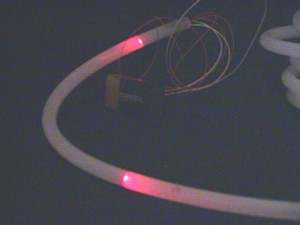
Posted: 2005-February-26 Filed under: Lighting, Projects, The Bike With 2 Brains Leave a comment »I tried out my idea of illuminating the polyethylene tubing and want to make sure a 12-inch spacing will look good enough. I quickly threw a test rig together and found the red clear LED's drop 2.2 volts, so the red LED needs a 340 ohm resistor for 20 mA with a 9-volt source. The red was adequate at a 12-inch spacing, throwing light about 3 inches down the tube — testing with brighter LED's should yield more perceived distance.


Recent Comments