Buy ball bearings
Posted: 2005-March-3 Filed under: Power Source, Projects, The Bike With 2 Brains Leave a comment »I hunted around on the Internet for ball bearings to fit a 5/16" shaft but wasn't having any luck. When I switched to metric — realizing that 5/16" is just 0.8% shy of 8mm — I discovered that I should be looking into inline skate bearings. I bought a pack from Pleasure Tools.
Survival calculations
Posted: 2005-February-28 Filed under: Power Source, Projects, The Bike With 2 Brains Leave a comment »I wondered what kind of forces the windmill will need to reckon with in strong winds. I found a g-force calculator on the Internet and determine that a 9.2-inch rotor (4.6-inch radius) running at 2,100 RPM (the speed I calculated for a 70 mph wind) will exert 578 g. Therefore, if there's one ounce of material at that radius — ergo an imbalance of one ounce — it will exert 36 pounds of force. Although I think 5/16" rod will easily handle 36 pounds of force, it's the 30 cycle-per-second vibration that might kill something.
I guess I have to be careful about balancing it.
Pulse-width modulated LED test
Posted: 2005-February-28 Filed under: Lighting, Projects, The Bike With 2 Brains Leave a comment »I played with a pulse-width modulated LED. The circuit wasn't pretty, but it worked … essentially a transistor amplifier that drives one differential input on an operational amplifier and the other is through a variable resistor set somewhere between the rails. The op-amp output drove an NPN transistor's base and the emitter was tied to ground. The collector went through a 1-ohm resistor through the LED to a 5-volt source — essentially, when the transistor was on, current followed a path through the LED, resistor, and the collector-emitter junction.
The peak-to-peak voltage on the 1 ohm resistor was 190mV, so in theory, I could have driven the LED to 200 mA average. The pulse-width modulator had a period of about 2.05 ms. The LED was barely on with a duty cycle of 14 µs which correlates to an average of 0.14 mA. It was "dim" around 50 µs or 4.9 mA. I considered it "fully on" at 134 µs which correlates to 13mA and "overdriven" by about 335 µs or 33mA. It appears the circuit works perfectly (and it doesn't appear to blow out the LED's.)
I also picked up some gray ribbon cable which I'll use inside the tubing to wire all the LED's.
Test polyethylene tubing
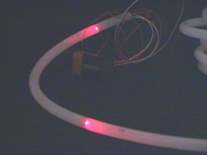
Posted: 2005-February-26 Filed under: Lighting, Projects, The Bike With 2 Brains Leave a comment »I tried out my idea of illuminating the polyethylene tubing and want to make sure a 12-inch spacing will look good enough. I quickly threw a test rig together and found the red clear LED's drop 2.2 volts, so the red LED needs a 340 ohm resistor for 20 mA with a 9-volt source. The red was adequate at a 12-inch spacing, throwing light about 3 inches down the tube — testing with brighter LED's should yield more perceived distance.
Savonius rotor test
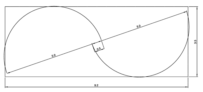
Posted: 2005-February-18 Filed under: Power Source, Projects, The Bike With 2 Brains Leave a comment »I thought I bought 6" round duct pipe, but apparently it's actually 5" in diameter. Anyway, I played with it a bit and figured I could make a neat rotor using a 2×4. I put it in the CAD software to get the dimensions (note also that I'm using a 10% gap between blades at the axis which is recommended by most people.
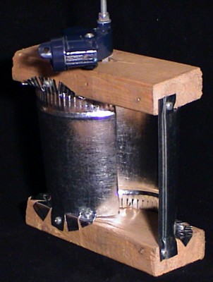
The idea was to notch the ends of the pipe halves and bend them into tabs to screw onto 2×4's. I wanted to ensure that one tab extended to screw into the end of the 2×4 and that the arc of the pipe fell tangent to the edge of the 2×4 so I could put another screw in the side through a tab. What I found was to cut the 2×4 to 9.2 inches long.
I learned that it was important to ensure the bent tabs form parallel planes. My first rotor came out crooked … not by too much, but enough that it would vibrate like mad in even modest wind. (By the way, that's the axle from a baby stroller wheel that I used as a pivot point to test it.) That, and I should alternate my cut tabs inward and outward so they don't overlap on the inside of the curve. Oh, and that you can only screw into tabs that are on the outside of curve — I guess unless you've got a short screwdriver or make the pipe segments longer than I did.
The best part, though, is that the rotor is very rigid. I'll be more diligent about the next design, and I sure hope it will survive strong winds.
Computer hard drive windmill
Posted: 2005-February-2 Filed under: Power Source, Projects, The Bike With 2 Brains Leave a comment »I started with the spindle motor from an old hard drive. I figured it was a pretty nifty use: the permanent magnet 3-phase motor should make a cool generator, plus it will supply 3-phase power. Unfortunately, my hopes of hitting 20 watts with it are pretty much dashed.
I cut out a Compuserv CD into fan blades, heated it to bend them, and mounted it to the motor. With the air hose, I managed to get to 600 RPM (a far cry from the rated 5400 RPM) and dumped 30 volts into 1000 ohms for a power output of 0.9 watts. Indeed, the power rating on the drive indicated it was only supposed to draw about 6 watts total, so my chances of getting past 5 watts or so is not too likely. However, even 5 watts over 20 hours would provide me with enough power to run 10 watts of lighting and other stuff for 10 hours or so. At least the 100 watt-hours generated each day is far more than the 50 watt-hour capacity of the batteries I'm looking at. Oh, then I broke the blade.


Recent Comments