Create full-scale eyes to test pipe bender
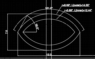
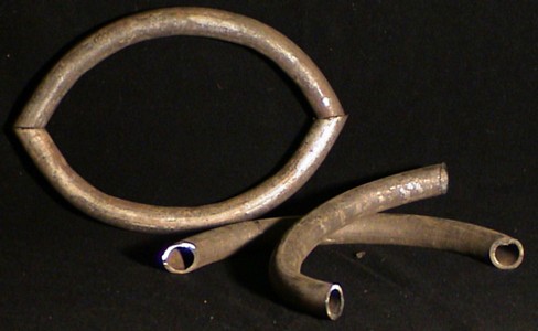
Posted: 2005-March-17 Filed under: Frame, Projects, The Bike With 2 Brains Leave a comment »I decided to build the eyes first. I have some pieces of Schedule-type steel pipe which I wanted to make sure the pipe bender I have can actually bend it — and in a controllable way. I also tested to see if I would have to strip the pipe to bare metal but it appears I can just use a wire brush to knock off the loose zinc and rust for the paint to stick.
Complicated capacitor LED driver model test
Posted: 2005-March-11 Filed under: Lighting, Projects, The Bike With 2 Brains Leave a comment »I decided to do the "LED experiment:" how fast can I charge a capacitor with a silicon 2N4123 transistor current follower — something like 10 µF — and how long will it for its charge to dissipate through the LED? In other words, how many LED's can I continuously refresh using this technique? My 20 mA LED that drops 2.2 volts will need about a 340 ohm resistor. It takes about 240 µs to charge a 5 µF capacitor to nearly full voltage — about 500 µs to squeeze in the last few millivolts. Dissipation takes only 650 µs to fall a full volt.
After a few iterations, I settled on a Darlington follower which drops the charge-time to 20 µs. Given a 1 µF capacitor, the rise time is below 10 µs and the decay runs for about 215 µs. If I move up to a 5 µF capacitor, the rise time stays below 10 µs but the decay jumps to 650 µs. If I then move up to a 10µs capacitor, the decay of 1 volt loss jumps to 1.4 ms.
Comparing to the prior pulse-width modulated test, I found the duty cycle needs to be about the same for the same brightness: 28 µs of the 2.1 ms cycle time or 1.3%, so I can theoretically drive 75 LED's in a perfect world.
Frame disassembly brainstorm; unicycle lament
Posted: 2005-March-7 Filed under: Frame, Projects, The Bike With 2 Brains | Tags: pipe, pipe union, unicycle Leave a comment »I decided I can use 3/4" pipe unions (which are three-piece deals; two of which have threaded ends and the third is a nut that keeps the two other parts together. They are beefier than typical pipe so they should be strong enough. Unfortunately, they're about $3.50 each so I'd like to see if I can find them as they are removed from old construction.
I also noted that even on eBay, the base price for a unicycle is $75 with shipping. Unicycles.com has the "cheapest" unicycles which sell for $63 with $12 shipping. On eBay the situation is worse with sellers using exorbitant shipping costs to offset low prices. So far, $75 is pretty much it.
Buy MP3 player
Posted: 2005-March-5 Filed under: Audio, Projects, The Bike With 2 Brains Leave a comment »I bought a Digisette Duo-MP3 from eBay. It has 32 MB of on-board flash RAM. Experimentation demonstrated that the player will handle monophonic, variable bit-rate recordings and output "acceptable" fidelity at 56 kilobits per second yielding over an hour of play time. The player supports mechanically-actuated forward, reverse, stop, volume-up, and volume-down buttons. These buttons appear to be able to be emulated using solid-state hardware and wired into the circuitry of the player without difficulty.
Original frame design and first copper wire model
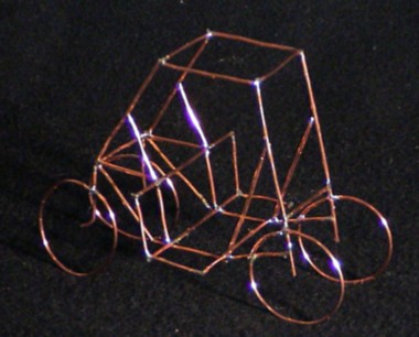
Posted: 2005-March-3 Filed under: Frame, Projects, The Bike With 2 Brains | Tags: frame, model Leave a comment »The bulk of the frame is a pair of direct-drive bicycles placed two-feet apart. Triangular parts maintain structural integrity and an overarching roof structure provides support for the windmill generator and to resist bending from the rigors of pedaling.
All four wheels are 24-inches in diameter and the rear wheels caster to allow the front wheels to provide steering as well as propulsion.
The frame has been modeled in 1:15 scale using copper wire. The material and scale were chosen because they were convenient. Although balsa wood and glue would also have worked, 14-gauge copper wire and solder were more readily available. The scale was chosen by printing the CAD drawings on an 8 1/2" by 11" page and then cutting the wire according to the lines on the page.
Buy ball bearings
Posted: 2005-March-3 Filed under: Power Source, Projects, The Bike With 2 Brains Leave a comment »I hunted around on the Internet for ball bearings to fit a 5/16" shaft but wasn't having any luck. When I switched to metric — realizing that 5/16" is just 0.8% shy of 8mm — I discovered that I should be looking into inline skate bearings. I bought a pack from Pleasure Tools.
Pulse-width modulated LED test
Posted: 2005-February-28 Filed under: Lighting, Projects, The Bike With 2 Brains Leave a comment »I played with a pulse-width modulated LED. The circuit wasn't pretty, but it worked … essentially a transistor amplifier that drives one differential input on an operational amplifier and the other is through a variable resistor set somewhere between the rails. The op-amp output drove an NPN transistor's base and the emitter was tied to ground. The collector went through a 1-ohm resistor through the LED to a 5-volt source — essentially, when the transistor was on, current followed a path through the LED, resistor, and the collector-emitter junction.
The peak-to-peak voltage on the 1 ohm resistor was 190mV, so in theory, I could have driven the LED to 200 mA average. The pulse-width modulator had a period of about 2.05 ms. The LED was barely on with a duty cycle of 14 µs which correlates to an average of 0.14 mA. It was "dim" around 50 µs or 4.9 mA. I considered it "fully on" at 134 µs which correlates to 13mA and "overdriven" by about 335 µs or 33mA. It appears the circuit works perfectly (and it doesn't appear to blow out the LED's.)
I also picked up some gray ribbon cable which I'll use inside the tubing to wire all the LED's.
Survival calculations
Posted: 2005-February-28 Filed under: Power Source, Projects, The Bike With 2 Brains Leave a comment »I wondered what kind of forces the windmill will need to reckon with in strong winds. I found a g-force calculator on the Internet and determine that a 9.2-inch rotor (4.6-inch radius) running at 2,100 RPM (the speed I calculated for a 70 mph wind) will exert 578 g. Therefore, if there's one ounce of material at that radius — ergo an imbalance of one ounce — it will exert 36 pounds of force. Although I think 5/16" rod will easily handle 36 pounds of force, it's the 30 cycle-per-second vibration that might kill something.
I guess I have to be careful about balancing it.
Test polyethylene tubing
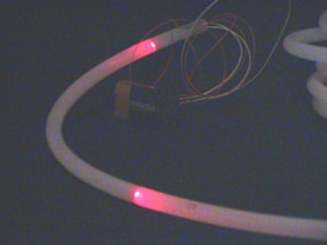
Posted: 2005-February-26 Filed under: Lighting, Projects, The Bike With 2 Brains Leave a comment »I tried out my idea of illuminating the polyethylene tubing and want to make sure a 12-inch spacing will look good enough. I quickly threw a test rig together and found the red clear LED's drop 2.2 volts, so the red LED needs a 340 ohm resistor for 20 mA with a 9-volt source. The red was adequate at a 12-inch spacing, throwing light about 3 inches down the tube — testing with brighter LED's should yield more perceived distance.
Savonius rotor test
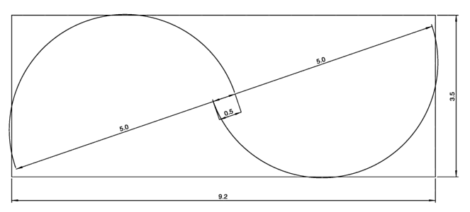
Posted: 2005-February-18 Filed under: Power Source, Projects, The Bike With 2 Brains Leave a comment »I thought I bought 6" round duct pipe, but apparently it's actually 5" in diameter. Anyway, I played with it a bit and figured I could make a neat rotor using a 2×4. I put it in the CAD software to get the dimensions (note also that I'm using a 10% gap between blades at the axis which is recommended by most people.
The idea was to notch the ends of the pipe halves and bend them into tabs to screw onto 2×4's. I wanted to ensure that one tab extended to screw into the end of the 2×4 and that the arc of the pipe fell tangent to the edge of the 2×4 so I could put another screw in the side through a tab. What I found was to cut the 2×4 to 9.2 inches long.
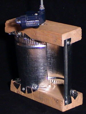
I learned that it was important to ensure the bent tabs form parallel planes. My first rotor came out crooked … not by too much, but enough that it would vibrate like mad in even modest wind. (By the way, that's the axle from a baby stroller wheel that I used as a pivot point to test it.) That, and I should alternate my cut tabs inward and outward so they don't overlap on the inside of the curve. Oh, and that you can only screw into tabs that are on the outside of curve — I guess unless you've got a short screwdriver or make the pipe segments longer than I did.
The best part, though, is that the rotor is very rigid. I'll be more diligent about the next design, and I sure hope it will survive strong winds.

Recent Comments