Debugging the Dead Power Supply
Posted: 2005-August-12 Filed under: Power Source, Projects, The Bike With 2 Brains Leave a comment »I don't think I mentioned it (and am too lazy to scroll down to check) but a friend of mine stopped by the other day and I was showing her all the stuff I've built so far. I loaded the switching power supply with 3 ohms to demonstrate the noise I get, but later I realized the -5 volt output was no longer working … odd. Tonight (Friday, by the way, and yes, I have had a few drinks — a chilled shot of Ouzo, a Saranac Pale Ale, and a Genesee can at home) I checked the power supply and inexplicably, the LM324 died — the op-amp that controlled the pulse-width modulation stayed at the positive rail for no reason. I pulled it and threw it away, even though it might have just as well been a loose connection. Replacing it worked just dandy. I tried connecting every LED — both strings, all three colors — and the input drew 0.53 amps for 0.76 amps out (in power, that's 6.36 watts in for 3.8 watts out for an efficiency of 59.7% — cool: almost 4 watts of output through LED's!) Anyway, I decided that the switching noise wasn't going to be much of a problem. Even with all three colors on one string lit, the noise is noticeable but ignorable … it adds an element of irritation. If I go to just one color lit (which, technically, is the load under bit modulation) the noise becomes nearly inaudible except very close. I have my fingers crossed.
Almost 100% done with the light tubes
Posted: 2005-August-11 Filed under: Lighting, Projects, The Bike With 2 Brains Leave a comment »I wired up the second light tube and had a case of deja-vu when I tried snaking it through the tubing: it was really tight and I kept breaking the wires I was pulling on. I used some silicone spray to try and get it going but it kept getting stuck. I eventually gave up, started on it the next day when I had some rest. I got it wired up and installed. I also found that I had a dead green LED in the original string so I replaced that. All I have to do now is to wire up the connectors … oh, and build the whole computer system.
Mom and Dad stop by
Posted: 2005-August-9 Filed under: Exhibitions, Projects, The Bike With 2 Brains Leave a comment »I got to show off the bike to my parents. My dad brought a couple parts I asked him to make: stand-offs for the computer control box. He was particularly impressed that it works and comes apart to fit into the car.

Me and my Dad, Frank Olshefsky, go for a spin.

Then me and my Mom, Joan Olshefsky, do the same.
The Savonius Windmill Generator
Posted: 2005-August-9 Filed under: Power Source, Projects, The Bike With 2 Brains Leave a comment »I decided that in this last week or so before I leave town, I'd pick up one more task: build a Savonius generator on the Bike With 2 Brains. So on Tuesday morning I got up and started thinking about designing it. I figured out that the bicycle seat posts are the right size to fit the "#608" size skate bearings — I had bought a pack of them because the 8mm hole is just a hair bigger than the 5/16" (7.99mm) threaded rod and bolts I planned to be using.
Wednesday I got up and started designing it in CAD. By 11 I came up with building a basic cube frame with a pair of centered cross-beams from side-to-side to hold the rotor. The key part is the detail below with the arm to hold the generator with a friction-coupling to the baby-stroller wheel (which is ultimately why I went with 5/16": it's the shaft diameter of the stroller wheel.) The diagram of this detail is below:

Windmill tensioner detail showing a bunch of circles and lines.
Basically, the rectangles on the left and right are the frame mounts and the center horizontal rectangle is the support bar. The small central circle is the bearing and the large circle is the baby-stroller wheel with the centered diagonal rectangle representing the 2×4 used for the rotor. The angled dimension lines surround the generator bar — the larger circle below the baby-stroller wheel is the motor housing and the smaller is the motor spindle (a wood dowel.) The line connecting the bolt (it's supposed to be a bolt and looks better in CAD zoomed in) is linked to the center frame by a spring.
I built a rotor that afternoon. The original one I designed had two problems: first, the shaft holes weren't well centered, and second, the top and bottom plates were not exactly parallel. I paid more attention to those two problems and things came out much better. I also used whatever remained of the vent pipe I had bought — it's just like the original prototype except that it's about 14" long. I even got the bearings mounted on the end and thought, "gee, that's it?" expecting it to be harder to make.
Thursday I got up and started working on the frame. I welded together a basic frame and rethought the cube shape: instead I went with a wide bracket for the rotor bearings and put the vertical members on either side of that. By that evening I had finish-welded the frame and tack-welded the brackets to mount the generator. It was almost hard to assemble it in the very light breeze because the rotor would spin so easily.
Friday I built the rest of the motor mount, mounted the preferred motor, and tested it against the fan in the attic — essentially the blower from a furnace. I was able to get about 4.5 volts open-circuit, 2 volts into 5 ohms (0.8 watts) and 1.5 volts into 3 ohms (0.75 watts.) I had to use a weaker spring than I started with because the friction of the stoller wheel against the dowel was too much when it was pulled tight. I don't know the wind speed nor the rotation speed, but it was pretty dangerous looking. I finished up the brackets and threw on some paint in the evening.
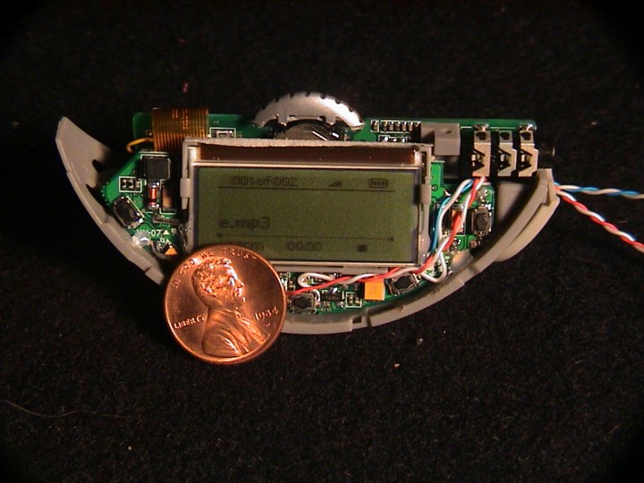
Hacking the MP3 player
Posted: 2005-August-8 Filed under: Audio, Projects, The Bike With 2 Brains Leave a comment »I took apart the MP3 player and did some measurements on the switches.
| State | Power button | Play button |
| off | 1.5V/0V | 0V/0V |
| on | 3.2V/0V | 2.8V/0V |
| playing | 3.2V/0V | 2.8V/0V |
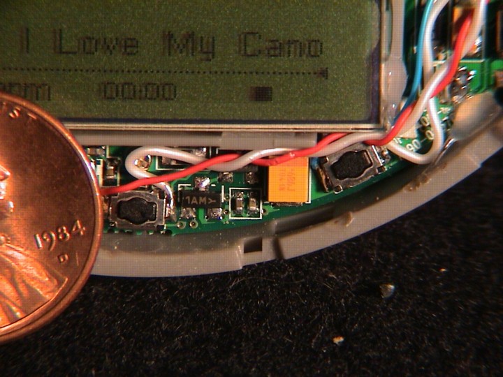
It's pretty convenient that I can detect power-on through the switch voltages. Whew. For playing I'll need to check that there's some signal on the output which could be a bit tricker. I think I'm going to compare to some arbitrarily low voltage and run the comparator output through a diode to a capacitor. The capacitor would discharge slowly with a resistor through the base-emitter junction of a transistor: the collector could be attached to a resistor to 5 volts — while playing, it would stay very close to 0 volts (logic 0) but if there was no ouput, it would slowly rise to 5 volts, eventually tripping whatever logic input.
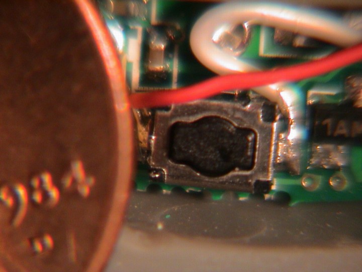
I wired up little wires to the switches and battery case to hook it to the logic circuits and power. What a pain to solder to this surface-mount stuff:
A quick note about emergency lighting
Posted: 2005-August-8 Filed under: Lighting, Projects, The Bike With 2 Brains Leave a comment »I've been thinking about what would happen if the main battery went dead — the whole vehicle would go dark and silent. I had been thinking about adding separate markers on the steering tubes of the back wheels, but it would quite a bit of extra work. It dawned on me that I can set up emergency lighting with a relay and a couple batteries: as long as the power was on, the relay would stay on; if it shut off, the battery would connect to several of the lights on the string: i.e. far front, far rear, and the eyes … 6 lights at 20mA would be 120mA and would drain a 2200mAH battery in 18 hours, but if I got it down to say 10mA total, then it would last for 200 hours. If I went with green then it would be most visible. I dug up a very small relay with a 12-volt coil and it draws 15mA itself, but I found I could get it down to 7mA if I wired it in series with a capacitor (to let it latch) and a resistor (to keep it latched.)
I changed my mind and decided to make a pulse-width modulator with a low-power 555 timer and just hold the reset pin low via the control computer — if it failed, the 555 would start pulsing and drive the LED's.
Finally sounds like it's working
Posted: 2005-August-6 Filed under: Audio, Projects, The Bike With 2 Brains Leave a comment »I'm using some DC-blocking capacitors to get the MP3 player output (which is grounded at -5V) to match the audio amplifier (grounded at -12V.) Unfortunately, I keep getting 1KHz noise from the switching supply. I tried going to the linear supply but that didn't work either. I even tried a big filter capacitor right at the MP3 player but no joy.
I figured out that the MP3 player was generating clean output but the speaker amplifier had issues with its ground being noisy. I tried a number of filtering techniques and such but came up dry. I decided to try with the LA4445 amplifier again: I figure I can bend the 2mm pins to fit the 0.10" spacing on the circuit boards I have. It dawned on me that I could probably make some kind of common-collector amplifier in a class A-B configuration.
I figure I can connect a resistor from emitter-to-base on each pole and one from base to a common input. The ratio of resistors defines the quiescent current and the values define the amplification. I may avan be able to do a push-pull with the 5-volt source for lower power and higher efficiency. I could set up the output to center around the -5V which is signal ground for the MP3 player. I thought about it for a while and decided to go with a common-emitter design with some biasing resistors and an op-amp — using the op-amp to compensate for the transistor switching.
First I tried the LA4445 because I thought it would be simpler. I spent an hour or so working, got everything wired up, but I took some shortcuts and the thing just won't work. Crap. Back to square one — again.
I decided to tinker with the transistors a little. I got to the point that I could generate output, but they won't stay on all the time in a true A-B configuration so it gets all noisy and such. I considered using some resistors and diodes to keep the transistors biased all the time.
I fianlly got a viable solution. I used the same crappy design I used for the amplifier I built years ago which just drives a couple opposed Darlington transistors with an op-amp as feedback, although I did a better job of fixing the high-frequency oscillation problem. It ends up drawing about 400 mA (5 watts) with the MP3 player in-circuit and the amplifier at volume with both speakers driven in parallel. I suspect that the output is around 2 watts total or so, based on around 2 volts RMS (as measured by the oscilloscope) into 2 ohms. If it hits 2.5 volts, it's at 3.1 watts which I think is about peak.
Based on the circuit I used, the input is already self-centering around the midpoint of the power supply. The transistors need 1.2 volts peak-to-peak to maintain quiescent current, so the theoretical maximum output (going rail-to-rail) is +/- 5.4 volts; RMS voltage is 3.8 volts or 3.6 watts into 4 ohms. I tried to get away with a single op-amp to do voltage gain and to power the main amplifier. It seems to work but is even more twitchy than before … although I guess the noisy volume level is so quiet that you'd have to be right next to the speaker to discern it. Here's the circuit:
I had an op-amp I was using to generate a solid signal ground, but I didn't need it so I took it out. Anyway, at the 12-volt source, the audio section (with the MP3 player draws about 50mA and when it's at full volume, it peaks around 200mA, so I assume the output power is around 1.8 watts total consuming some 2.4 watts at peak volume. It kind of sounds like crap with a bit of fuzzy distortion from the transistor switching noise — if you know circuits, it should be pretty evident why:

A simple but lousy amplifier.
I got the amplifier wired and it works okay from the linear power supply but it's not working off the battery and I'm not sure why. It dawned on me that I can just use one of the op-amp's as a differential amplifier off the MP3 player and feed that into the prefabricated amplifier? I ended up with this simplified circuit:

The op-amp tends to avoid power-supply noise.
The first experiment worked great so I rewired the circuit to take out all that extraneous crap to deal with the transistors and got it working again. It looks like I can get something like 3 watts of audio out of the thing, and the whole powered system typically takes around 2 watts at moderate volume.
It's just too bad I had to ditch the power transistors and heat sinks because they really looked cool.
The pretty-good 12V-5V DC-DC converter
Posted: 2005-August-5 Filed under: Power Source, Projects, The Bike With 2 Brains Leave a comment »I put the power supply on a board and wired it all up. I figure I'm getting around 60-65% efficiency — far better than the 42% efficiency of using a linear regulator. In other words, if my lighting stuff (the motivation for the 5-volt supply in the first place) outputs 1 watt, the battery will be hit with 1.5 watts whereas if I had used a linear regulator, it'd see 2.4 watts — the 84 watt-hour battery could run for 56 hours instead of 35 hours. Heck, it's almost half as much time as I put into making the fucking thing!
5 volt success on the breadboard
Posted: 2005-August-4 Filed under: Power Source, Projects, The Bike With 2 Brains Leave a comment »I got around to the basics of the circuit below. I set up the MOSFET in the configuration below and drove it from the op-amp. I added the PNP in a similar configuration to ensure that maximum current would get to the gate — I need to get that gate to 12 volts, and the 20 mA output on the op-amp wouldn't cut it. I got nice square square-waves but, using a simple pulse-width modulation to the capacitive output, I was getting the same problem of current-in equals current-out. I set up the buck configuration again and finally got some success: 6.6 watts in and 4.2 watts out for an efficiency of 63%.
At this point I realized the output-as-driven would end up as 5-volts from the positive battery rail. I remembered having 7905 negative-rail 5-volt regulators around (and always thinking, "what the hell will I ever use these for?") I switched to the terminology where the positive battery terminal was ground (calling it 0-volts) and the negative rail was -12 volts. I spent some time diagramming the circuit (using CADintosh from Lemke Software, GMBH.) I went back and set things up like I had drawn, made a few changes, and did some final tests on the breadboard. By varying resistors, and using the 51-ohm load I got 97mA out (4.95 volts at 470 mW) with 52 mA at the input (624 mW) for an efficiency of 75%. I tried the 8-ohm load and got 620mA out (4.96 volts at 3.08 watts) with an input current of 419 mA (5.03 watts) which gave me an efficiency of 61%. I think this looks pretty good.
So, after three days of slaving for a total of 20 hours or so, here's the circuit …

Here's the final (so far) circuit diagram for the inverter.
You can look up explanations for a twin-T oscillator and a buck converter for the oscillator and the inductor on the Internet, but one thing that I don't think is too obvious is that the diode after the op-amp is there so the base of the PNP transistor can actually go to the rail — the op-amp may not reach it, but the diode will be shut off so the 470-ohm resistor will shut the transistor down. The other thing is that the inductor has no value. I don't know what it is: it's a yellow torroid with red magnet wire that I pulled out of a dead computer UPS, so I don't know its value, but of the ones I had lying around, it worked best. I guess I should put parallel lines below it because it's iron-core … oh well.
DC-DC converters via the 10-potentiometer method
Posted: 2005-August-1 Filed under: Power Source, Projects, The Bike With 2 Brains Leave a comment »First, the "10-potentiometer method" is when you have the basic idea for a circuit but tune it by varying values until it works the way you want. That's basically where I started.
The general idea is that I wanted to make a high-current source for the 5-volts I'll need to run the logic circuits and LED's (I wired the LED's to expect 5-volts on the input resistor) that's pretty clean, but it doesn't have to be perfect. I knew I didn't want to start with a linear supply: if I went from 12 volts to 5 volts, the power efficiency is 42% (i.e. at 1 amp it's 12 watts in for 5 watts out and 5 watts / 12 watts = 42%.) However, I also didn't want to go with an off-the-shelf solution — mostly because I thought my requirements were really easy.
I got up on Monday, August 1 really early and got started. I dug through my transistor bin to find an NPN that could handle around 3 amps. When I started I figured I could go from 12 volts to half that (6-volts) and then drop the rest through a 7805 regulator to give a nicely cleaned-up output.
I got a buck-style converter set up. It was similar to the circuit above — using the twin-T oscillator as a source for pulse-width modulation on an op-amp — but I didn't use the 7905 and just had a couple 100K resistors on the input pin of the feedback op-amp to approximate 6 volts, I didn't have a high-pass filter on the feedback circuit, the oscillator was running from +12 volts to 0 (or 0 to -12 volts as I've got it diagrammed) and the output was just a current follower where I had an NPN set up with the base tied to the output of the PWM op-amp (top right) with its collector tied to battery-positive, and the emitter driving the diode/inductor/capacitor buck setup.
I ran 127mA through 51 ohms to get 6.7 volts (850 mW) and I was able to source 5 volts at 1 amp into 5 ohms (25 watts) although it seems to go linear. I suspect the transformer I'm was using as an inductor doesn't have enough current capacity. I tried 8 ohms and managed to source 800mA at 6 volts (2.4 watts) and that seemed to be the limit of the power source before going linear (the transistor was on at over a 90% duty cycle.) With that output current, I checked the input and it was drawing around 650mA at 12 volts or 7.8 watts — hardly efficient at all at 33%. With the 51-ohm load, it uses 130mA just like the output … then again, maybe my meter just isn't very good at measuring transient currents like the circuit is drawing from the battery. I used the oscilloscope instead so I could estimate the waveform (and actually calculate RMS voltages) with an 0.1 ohm resistor — a handy value for converting to current (volts times ten.)
I tried some differnet chokes and found one that would cause the circuit to input 700mA RMS (2A peak-to-peak) at 12 volts (8.4 watts) for an output of 1 amp into 8 ohms (8 watts) so that's pretty good (although for some reason it decides to output 8 volts instead of 6 volts.) I tried switching to another op-amp (now the LM324 which is what I stuck with throughout) figuring that it could get its output closer to the rails — that got me to around 65% at 8 ohms but only 24% at 51 ohms, but running that inefficiently, I would expect 2 watts dissipated on the bare transistor to get hot really fast … hmm … I'm concerned about my measuring efficiency. I tried estimating the waveform power levels with some calculations and got to a 45% efficient — worse than the 50% efficiency of just dropping half the voltage as a resistive load.
I kept switching coils, transistors, and resistors. Man am I sick of staring at breadboards and oscilloscopes. I got varying figures and even created perpetual motion machines: I had a 115% efficiency at one point. I was certain it was measurement error.
Up until now, I was using a linear power supply for the 12-volt input. When I switched to the battery, everything stopped working. I had to start all over again — I tried varying the frequency of the PWM oscillator then I tried removing the feedback loop to see if I could get something out unregulated and met with some success. I also floated the PWM oscillator (oh yeah: originally I had the emitter tied to ground, so the oscillator was running very close to the rails.) I added a filter capacitor at the input. All this helped but didn't get me any closer to something that could significantly beat a linear supply.
I decided to check my 0.1 ohm resistor to make sure it's good. Using the meter, I measured a 203 ohm resistor in series with the 0.1 ohm and measured 12.67 volts across it (when I hooked the two series resistors across the battery) for a current of 62.41mA. The 0.1 ohm resistor dropped 0.0123 V so the resistance is actually 0.197 ohms. Once I figured that out, all my efficiencies were twice as good. I took a break and enjoyed the catharsis, but I really didn't believe my measurements so I went back and did them again. Using a 303 ohm resistor, I get 12.74 volts across it which is 42mA and I measured 4.0 mV across the 0.1 ohm resistor, making it 0.095 ohms. Darn. I tried the other resistor: it now reads 205 ohms and dropped 12.70 volts or 61.95 mA. Given the 5.9mV drop on the test resistor, I get 0.095 ohms again.
I tried making a PNP current source to drive the NPN current follower off the op-amp … somewhat similar to what I've got above, but the PNP output goes to an NPN current follower. That gave me an efficiency of 42%. I stripped the circuit back to the point that the transistor is switching a full 12 volts on-and-off at a 50% duty cycle, and still it has a 50% efficiency. The collector-emitter voltage switches between 12-volts and 1.5 volts, but that only accounts for some of the inefficiency. I decided to try a MOSFET in the same configuration but got the same result.
Tuesday I got up early again and I figured the feedback loop was giving me trouble by switching off the resistors too soon regardless of the high-pass filter I added yesterday. I thought about using a sample-hold circuit on each pulse, but then thought that was stupid and would be a waste of time. Instead I figured that the output transistor can't get fully on or fully off based on the op-amp. I couldn't figure out what to do about it. I tried using a buck-boost configuration where the inductor is in parallel to the output but that didn't work. Heck, the inductors had no appreciable effect at all.
Once I did some measurements, I figured out the big problem. The MOSFET output was swinging from 0 volts to 8.1 volts when using the 8-ohm load. That 4 volts at 670 mA (6 ohms) with 50% duty cycle accounts for 1.3 watts of power loss (out of a total input of around 8 watts and an output of 3.5 watts, so there's still some 3.2 watts going somewhere I haven't found yet.) I tried the 51 ohm load and the peak is around 9.1 volts with a current of 120mA but with about a 30% duty cycle — 75 ohms this time accounting for 360 mW out of a total loss of 710 mW. I checked, and if I supply a full 12 volts to the gate of the MOSFET, the maximum output is only 9.1 volts into 51 ohms. Harumph.
I switched to some 2N277 PNP transistors I had lying around in the switch-configuration I have on the first stage of the output in the circuit above. However, that didn't work. I tried the more reliable small-signal PNP's but that didn't work either.
Recent Comments