More rear-end redesigning; first welds
Posted: 2005-April-5 Filed under: Frame, Projects, The Bike With 2 Brains Leave a comment »I found that I had some problems in the back end. First, the tubing I expected to use was longer than any bike tubes I had, so I made them all shorter. However, I had drawn the wheels castering backwards: if the wheel were to spin 180 degrees from where I had drawn it, it would strike the frame.
The forks I have vary but the axle was typically 2"-2.5" from center — I had estimated 3 inches in my original drawing. I also measured the distance from the bottom of the steering bracket to the top of the wheel, and that's about 4 inches, but I had only given 1 inch in the original drawing so I increased it and adjusted the other parts. In the process, I added some more support.
I worked on the bike frames and cut enough pieces to make one side of the rear of the frame. I wasn't going to have enough time before sunset to finish the frame, but I did get out and weld the eyes together. There were a few strokes of the welder that went really well, and as I went, I improved. I had to grind a lot of material away to get it to a reasonably attractive shape, but it otherwise looks pretty good.
Generators #4: A New Hope — AC generators
Posted: 2005-April-2 Filed under: Power Source, Projects, The Bike With 2 Brains Leave a comment »I figure I can easily convert a DC motor to an AC motor by tying one side of the rotor windings to both sides of the brush assembly rotor thing, and the other side to the shaft. That way I can step up the output voltage to a useable level.
I went to the basement and grabbed all the motors. I decided to try converting the drill motor since it generated the highest current (next to the original) and it's the largest. I decided against the air pump motor because, although it can source a lot of current, the output voltage is so low it's almost not worth it … then again, that's based on running it up to 3,100 RPM on the drill press, not the huge speeds from spinning on the rubber wheel.
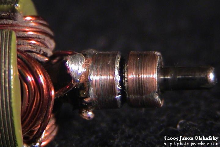
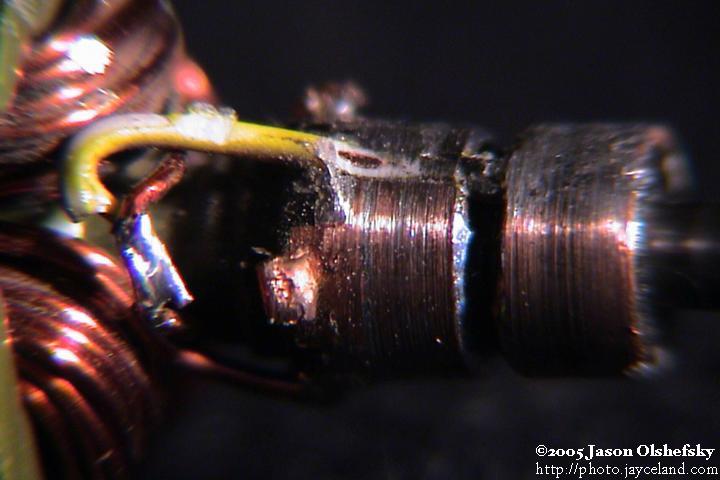
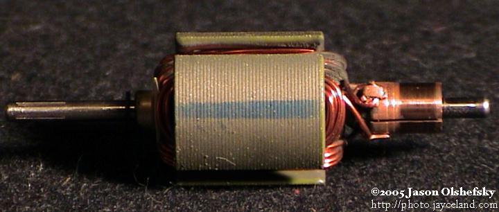
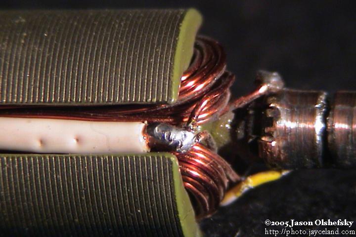
Anyway, I took apart the gold-colored motor and rewired it. I started by cutting a groove around the commutator and soldering the original poles together so I ended up with a 2-pole slip-ring instead of a 3-pole commutator. I ground down the brushes so each would contact one pole of the slip-ring. I disconnected the three poles, undid the connection that tied the windings in a loop and connected each end to the slip-ring contacts.
When I reassembled it and tested it, I roughly zero volts out. I had successfully demonstrated that the motor was wired efficiently and Kirchoff's laws still apply: of course there was no current flowing at that point — otherwise, when run as a motor, it would short-out. Dummy.
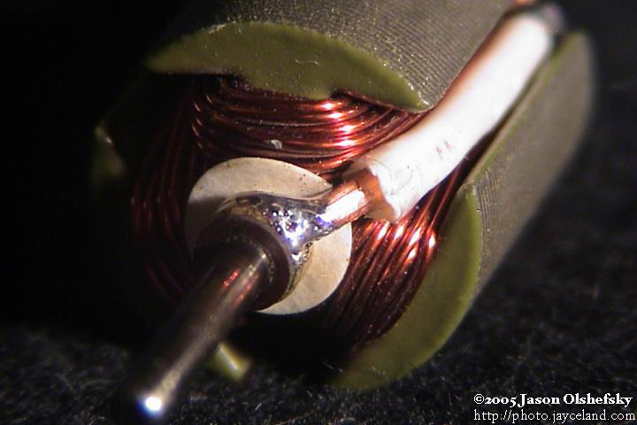
I took it apart again and wired it for 3-phase. Two phases were wired to the brush output, and the third was soldered to the shaft bushing so I could use the case as the third phase. It sort-of worked, but then the wire I was using to tie the third leg to the shaft came loose and wedged between the rotor and the magnets.
I reassembled the motor with a stiffer wire. I found that the brushes would bounce on the imperfect rings I had so they wouldn't transfer the power. I could get up to about 1 amp of output on any one coil and up to 1.5 volts or so. I cleaned up the rings and such but couldn't get them round enough with the tools I had so I gave up on it.
However, I also had an AC brush motor from a Dirt Devil hand-held vacuum and figured I could make a rotor with permanent magnets to induce current in the outer coil. Finally a break in all this: the rotor shaft was 5/8" which is the same size (well, 8mm) as the the bearings I bought for the Savonius rotor. Even better, the magnets in the gold-colored permanent magnet motor are very close to the right size.
Generators #3: Experimentation
Posted: 2005-April-1 Filed under: Power Source, Projects, The Bike With 2 Brains Leave a comment »I tested some of the motors at high-speed to see how much they'd generate and to see if any would be suitable. Note that the motor speed was dictated by the shaft diameter; the drill motor, 6V motor, and original motor had larger shafts and ran slower.
Motor
open
voltage
voltage
@ 3 ohms
power
@ 3 ohms
drill
> 4.7
4.6
7.0 watts
gold
> 4.5
4.6
7.0 watts
silver
> 3.0
3.7
4.6 watts
6V motor
> 6.5
4.6
7.0 watts
original
> 14.0
7.5
18.8 watts
For the stepper motor, at 1,100 rpm, using both phases through a bridge rectifier, it would source 0.63V into 3 ohms or 0.13 watts. One phase through a 5:1 step-up transformer frustratingly yielded the same results: 0.6V. Both phases in series yielded 0.67 volts, and at 1,720 RPM, 0.8 volts. The open voltage on the transformer secondary was 11.75 volts.
I also took apart one of the pumps that I used to use for the air horns in the car and got its motor separated. It could source 3 volts into 3 ohms and had a short-circuit current of 5 amps at 3,100 RPM.
Generators #2: Stepper motors suck as generators
Posted: 2005-March-31 Filed under: Power Source, Projects, The Bike With 2 Brains Leave a comment »I decided to go buy a motor so I went to Glenwood Sales (549 Hague St.) and browsed for a while before eventually settled on a 30 V stepper motor with a 48 ohm coil. It apparently has 4 phases, and each phase would ordinarily consume 0.625 A or 18.75 watts.
The stepper motor could generate as much as 50 volts open-circuit (it's wired with two coils center-tapped.) Through a 51-ohm load I found it could get as high as 5 volts, and through a 280-ohm load, 20 volts. The good news is it's pretty linear from about 1,000 RPM through 3,000. The bad news is those two ratings yield only 0.5 watts and 1.4 watts respectively.
Using a full-wave bridge on each side and tying the outputs together and running at 3,100 RPM, I could get 9 volts into 51 ohms and 34 volts into 280 ohms: 1.6 watts and 4.1 watts respectively. Open, it would generate 90 volts. Indeed, none of the motors would source more than a half a volt at 3,100 RPM; one that I hadn't tested would generate 0.5 V and 1.5 amps, so at least that's promising.
Notes on frame parts
Posted: 2005-March-28 Filed under: Frame, Projects, The Bike With 2 Brains Leave a comment »None of the bicycles I have currently have the correct dimensions for using the triangular front-end as-is on the back of the Bike With 2 Brains, so I'll have to custom build those parts. It's probably for the best anyway since I don't like the size of any of the top brackets.
Method of mounting the rotor bearings; Generators #1: These generators suck
Posted: 2005-March-28 Filed under: Power Source, Projects, The Bike With 2 Brains Leave a comment »I found that I have some 1" thin-walled tubing from an exercise machine that has a nearly 22mm diameter — the outside diameter of the bearings I bought. I figure I can weld a piece of tubing to the ends of the windmill frame then cut a slot and use a seat-post clamp to grip the bearing.
I also tested the motors I had selected as candidates for a 10-watt generator. None of them performed better than the motor I had originally selected.
Based on my former calculations, the rotors would only run at 300 RPM in a 10 MPH wind, so a 7x gear-up would only yield 2,100 RPM which wasn't enough to generate any appreciable power. To get any power out, I had to run the baby carriage wheel in the drill press at 620 RPM with a 0.33" gear, so the ratio to the 7 3/4" wheel (23.5x) means I ran the motor at 14,500 RPM. If this were 20 mile-per-hour wind, then a 70 mile-per-hour wind would overcrank the motor to over 50,000 RPM and probably blow it up. I'll have to see how slow I can get the motor to run and still get decent power. Well, I know that 3,100 RPM is not enough: the motor, when hitched directly to the drill press, would only generate about 3.4 volts open and 1.9 volts into 3 ohms (only about 1 watt.)
Ok, so let's say I limit the motor to 15,000 RPM at maximum wind speed of 70 MPH, or 2,100 RPM. The ratio, therefore, is 7:1 … bummer. I think I'm going to need to get a different motor. If I use 21,000 RPM as the cap, I can get to a ratio of 10:1, so in a 10 MPH wind, the rotors would only run at 300 RPM driving the motor at 3,000 RPM which isn't enough.
Get electronic components
Posted: 2005-March-25 Filed under: Computer, Projects, The Bike With 2 Brains Leave a comment »I ordered resistors, transistors, capacitors, and an analog switch chip from Mouser on the 19th and they arrived today.
Redesign frame
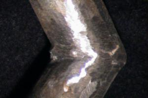
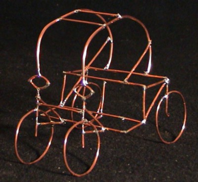
Posted: 2005-March-21 Filed under: Frame, Projects, The Bike With 2 Brains Leave a comment »I redesigned the frame with a rounded top and moved the rear wheels as wide as the edges of the seat. Prior to deciding to make the top frame rounded (which is an aesthetic choice) I had to make the eyes (in full scale) to test that I could indeed bend Schedule-style steel pipe with the hydraulic bender I have.
I moved the rear wheels further apart for aesthetic and practical reasons. Aesthetically, the copper model looks like forward is indeed forward owing to traditional conventions of wider wheelbases in the rear of vehicles. Practically, 24-inch diameter wheels would hit one another if the axis of rotation was only 24 inches apart.
I think it's a good decision because it'll improve stability as well — the only downfall is that it's not so clear how I want to make the whole frame come apart so I can transport it.
Ordering some of the parts
Posted: 2005-March-19 Filed under: Lighting, Projects, The Bike With 2 Brains Leave a comment »I noted that the full-spectrum LED's I'm looking at from LSDiodes.com have the following voltages: 2.05 volts for red, 3.2 volts for green, and 3.6 volts for blue; all at 35 mA. Thus, to be driven at full brightness from 5 volts, I'll need an 84 ohm resistor (the closest standard value is 82 ohms) a 51 ohm resistor, and a 40 ohm resistor (closest being 39 ohms.) The 84 ohm resistor will drop the most amount of power at 0.1 watts, so pretty much any size is safe. While I'm at it, driving one of these LED's with all elements on at full brightness is 310 mW, so if I'm to limit the lighting to 6 watts or so, I can only use about 20 LED's at a time … of course, I can just program it so it's not trying to turn on all the LED's white at once.
I put in an order at Mouser.com for the resistors (I had to swap the 82-ohm resistors for 75-ohm since they were out of stock) a bunch of 10 µF capacitors (I already have 48 so I bought 50 more, expecting to wire in no more than 32 LED's) and a bunch of 2N3906 PNP general purpose transistors that I'll use with 74LS138 3-8 multiplexer chips to drive the cathodes of the LED's.
Select microcontroller
Posted: 2005-March-18 Filed under: Computer, Projects, The Bike With 2 Brains Leave a comment »I ordered a PIC 18F252 8-bit microcontroller made by Microchip from SparkFun.com along with a development kit. It arrived a few days later. The whole thing is smaller than it looks in the pictures on the Internet … I'm looking forward to playing with it.

Recent Comments