Better DC-DC converters
Posted: 2005-July-14 Filed under: Power Source, Projects, The Bike With 2 Brains Leave a comment »I went back to using bipolar transistors and managed to make a circuit that could get up to 12 volts. I changed the output circuit to a darlington network to get more gain (hopefully.) The circuit was operating at an input voltage of 2.7 volts.
I tried switching to the 5-volt supply and I could comfortably get 12 volts into 220 ohms — 54 mA for a total power of 0.65 watts; with 51 ohms, I could get 8 volts or 1.3 watts. I'm pretty sure I'm up against the output capacity of the transistor at this point, so I tried a heat sink but it didn't help.
Anyway, in the process of digging around, I found this high-power NPN transistor. I hooked it up on the DC-DC converter and managed to drop 15 volts across a 51-ohm load with 5 volts in — a total of 4.4 watts. That's getting there.
Current limiting the new LED's
Posted: 2005-July-11 Filed under: Lighting, Projects, The Bike With 2 Brains Leave a comment »I originally bought resistors to use with the RGB LSDiodes.com but I realized the voltages and currents might be different. Indeed, the 3mm red/blue and 3mm green LED's require different values. I calculated the results with either a 4-volt or 5-volt supply (which I'll probably use.)
Color
Voltage
Current
Volts
across
resistor
Desired Resistor
red
2.2 V
20 mA
2.8 V
3.8 V
140 ohms
190 ohms
green
3.3 V
20 mA
1.7 V
2.7 V
85 ohms
135 ohms
blue
3.2 V
20 mA
1.8 V
2.8 V
90 ohms
140 ohms
Anyway, I tested using 150 ohm resistors for blue and green and a 180 ohm resistor on red. This balanced things so each LED was driven at about 30mA with a 7.5V source. The 150 ohm resistors dissipated 0.14 watts and the 180 ohm dissipated 0.17 watts, but with 20 mA, the figures are 0.06W and 0.08W respectively, allowing me to use 1/8W resistors. I also noted that I can use two layers of Scotch tape to diffuse the light nicely. I checked the circuit with 5 volts — green was 18mA, blue was 20mA, and red was 22mA — very close to ideal and easy to fix in software, so I went ahead and bought packs of 150-ohm and 180-ohm resistors.
More people in the back yard
Posted: 2005-July-10 Filed under: Exhibitions, Projects, The Bike With 2 Brains Leave a comment »I showed off the Bike With 2 Brains to my friend Sondra who had bought me a ticket to go to Burning Man in 2004 for my birthday. She was really impressed that I actually got as far as I have. Plus, it's insanely fun to ride. Later on, some new friends Elliotte and Sarah got to try it and they liked it as well. Sarah slipped off the pedal and hurt her foot a little, so I think I'm going to find some other pedals.
Building a better, stronger, faster fork
Posted: 2005-July-6 Filed under: Frame, Projects, The Bike With 2 Brains Leave a comment »One of the forks broke during a test on July 4. The wheel got stuck against a bump in the grass and wouldn't turn. When more force was applied at the front wheels, the axle slipped out of the slot in the fork causing all the force to be applied to one leg of the fork and the wheel axle. It bent both parts pretty good.
I noticed that I had used forks for 26" wheels so I did the same for this one. I created two more bent forks so I'd have a spare.

Nothing like spotting poop in your yard to get you to slip the nut off the side of the fork and bend it to uselessness.
Independence Day picnic
Posted: 2005-July-4 Filed under: Exhibitions, Projects, The Bike With 2 Brains Leave a comment »I got around to getting the vehicle out of the car and put together the front wheels. Now that I can see it in good light, the paint job is pretty dinged up — I'm not too happy that it chips as easily as it does. Anyway, I got to let some friends of mine try it out and they really liked it.
I think I damaged the back wheel when I was on the back end while Jan and Todd were trying to drive, but we kept going. Jan and I finally broke it in when Jan spied dog poop in my yard — and I don't even have a dog. Oh, but anyway, the cheaper-forked back wheel slipped out of the fork halfway, bending both the axle and the fork irrepairably.

Nothing like spotting poop in your yard to get you to slip the nut off the side of the fork and bend it to uselessness.
Make a shipping crate for some of the parts
Posted: 2005-June-30 Filed under: Frame, Projects, The Bike With 2 Brains Leave a comment »The title says it all: I made a wood box to hold the 6 straight bars for the vehicle. It's reasonably compact and keeps the bars from knocking against one another.
Video!
Posted: 2005-June-30 Filed under: Exhibitions, Projects, The Bike With 2 Brains Leave a comment »I packed the vehicle parts into the car (using the freshly made packing crate for the straight parts) and headed to Lux Lounge (666 South Ave.) Around 9:30 or so I got some help getting all the parts into the back yard. In all, I think it took about 30 minutes to get the whole thing assembled in the dark. I think about 12-16 people got a chance to try it out … I took some video and posted it on my other website a few weeks ago … same as here.
John and I took it to a nearby parking lot to see if we could get it to go straight. The traction was so much better than in the dirt that we actually broke one of the spokes on the steering wheels in back. In the end, we found it was pretty easy to get it to go straight backwards (although it's hard to get it to change direction) and it's probably impossible to get it to go straight forward (although it's easy to get it to go in circles.)
I had to take it apart in the dark too and I guess it also took 30 minutes or so. I got back home and was somewhat amused to find that my feet got the dusty clay dirt all over them. It was very reminiscent of the playa, except it didn't burn or anything.
(For a while I was using something called the Coral project to host the video, but it has apparently gone away.)
Basic DC-DC converters
Posted: 2005-June-26 Filed under: Power Source, Projects, The Bike With 2 Brains Leave a comment »I found a website that described DC-DC converter basics. I took a crack at building a "boost" style step-up DC-DC converter (where an inductor is placed in series with a power source and the output side is switched to ground.) I managed to step 5 volts to 24 volts across a 1.2K load (using low-power components) for a current of 20mA or almost 0.5 watts.
I found that transformers work particularly well in the circuit — plus, the secondaries offer useful voltages as well. By switching to better transistors (i.e. 2N2222 instead of 2N4123) I achieved 38V out into 1.2K: 32mA or 1.2W. This looks very promising … now if only I could get it to work from 1 volt.
I measured across 51 ohms and got up to 9.3 volts out. The input current is about 0.46A at 5.7V, so that's 2.62 watts and the output into 51 ohms is 0.18A or 1.70 watts out, so it's about 65% efficient. Using a smaller torroidal inductor, I got 8.62V into 51 ohms or 1.47W with 5.82V at 0.40A in or 2.34 watts for 62% efficiency.
I started building one to work off 1.5 volts or so. At first I didn't get it to work. I rebuilt the whole circuit and got exactly the same bizarre result: a short-cycle square wave that seems to ring down. I couldn't get the thing to work. The capacitor on the NPN transistor seems to be running into negative voltage territory somehow … it actually oscillates, but the final output is a stilted square wave. I switched to a (possibly more stable) twin-T design which I managed to get to work with as little as 3 volts.
I thought that I could try using MOSFETs but I couldn't figure out how to get them to work.
LED's with bit modulation
Posted: 2005-June-23 Filed under: Lighting, Projects, The Bike With 2 Brains Leave a comment »I met a guy named Dave who referred me to an idea for driving LED's with a microcontroller using a shift-register and latch with a technique called "bit modulation." It's a derivative of pulse-width modulation except it's much better suited to driving multiple outputs concurrently.
In traditional pulse-width modulation (I'll assume it's all for LED's although it can apply to any averaged output) the LED is driven at full-brightness for some percentage of the time at a relatively high frequency (enough that the human eye's persistence of vision can't detect the blinking.) So, for instance, to create the illusion of 10% brightness, the LED is turned on for 1 unit of time and then off for 9 units of time. Usually the frequency of the wave remains the same and only the duty-cycle changes.
In bit-modulation, the desired modulation is assumed to be a binary value. The least significant bit (2^0) is read and the LED is turned on or off depending on its value for 1 unit (2^0 units) of time. The same is done for bit 1 (2^1) only for 2 units of time (2^1.) This continues for successive bits. The resulting brightness output averages to the value over 2^(n+1) clock cycles — the illusion works as long as the LED is on for [duty-cycle]% of the time and off for 100%-[duty-cycle]% regardless of how many times the LED is turned on or off during a cycle.
The huge advantage here is that a shift-register with a latch can be used to set the values for any number of LED's in a very short amount of time. That is, if you have X LED's, the same bit from each of the X LED's desired duty-cycles can be shifted in to the register, the latch can be triggered, and then the CPU will wait for (2^bit) time units until the next bit is loaded.
Unfortunately, I'm using a system where the red, green, and blue anodes are on three wires and the common-cathode of each LED cluster is brought back on one wire — so for X LED's I need 3+X wires. I dismissed the idea — although really cool — because it just wasn't practical for what I wanted to do.
Assembling the painted frame
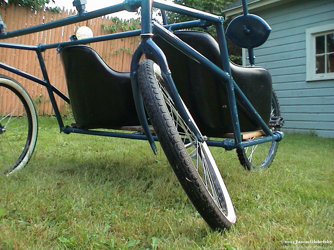
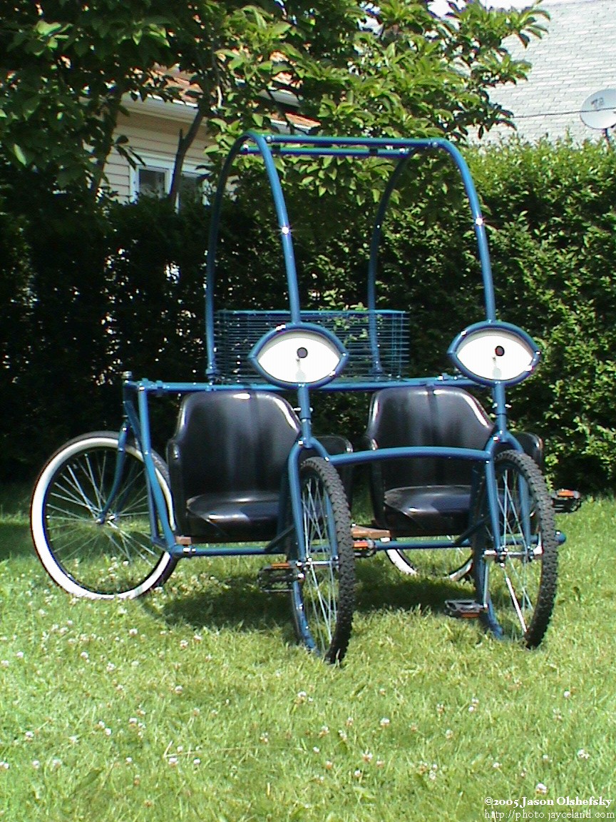
Posted: 2005-June-21 Filed under: Frame, Projects, The Bike With 2 Brains Leave a comment »I finally had a chance to put everything together with the office chairs and check it out. Some of the angles of the mounting points are off by a bit, but otherwise everything went together fine.


Recent Comments